Imaging device, portable terminal using the same, and image device producing method

a technology of image pickup and portable terminal, which is applied in the direction of instruments, color television details, television systems, etc., can solve the problems of reducing the maximum permissible size, reducing the pitch of pixels, and causing trouble in object image data

Inactive Publication Date: 2006-07-06
KONICA MINOLTA OPTO
View PDF3 Cites 30 Cited by
  • Summary
  • Abstract
  • Description
  • Claims
  • Application Information

AI Technical Summary

Benefits of technology

[0028] A first object of the present invention is to obtain with the above problems in view: an image pickup device that can prevent the dust entering from outside and the dust occurring during internal operation, from sticking to an image pickup element, and thus protect image data from trouble; and a hand-held terminal having this image pickup device.

Problems solved by technology

In addition, light-receiving sections for photoelectric conversion are arranged at pitches of several micrometers, and so if any dust particles blocking the flux of light incident on the object to be photographed are present on the microlens disposed on a light-receiving element, trouble will occur in object image data.
Increasing the number of pixels in image pickup devices intended to obtain higher image quality, however, reduces pixel pitches and correspondingly lessens the maximum permissible size of the dust sticking to the photoelectric conversion plane of the image pickup device.
Therefore, current situations are already posing the problem that even if there is any sticking dust that is too small to be visible with naked eyes, image data cannot be obtained since a photographic object light flux is blocked.
In this method, however, if microvibration or the like is applied to the device interior for a long time, dust arises from wear due to contact between the legs of the optical member and the isolation wall of a mirror housing / frame or from wear from the abutting sections between the legs and the image pickup element.
If the dust sticks to the upper face of the image pickup element, the drawback may occur that since a photographic object light flux is blocked, object image data is affected.
Also, during the zooming or close-up photographing that involves moving an image pickup optical system, mechanical linking to the operating member and driving member for moving the image pickup optical system is required, which permits outside dust to enter from the linking sections and causes a drawback similar to the above.
That is, image pickup devices for mounting in hand-held terminals are required to be as thick as possible in response to reduction in the thickness of the apparatus in which the image pickup device is to be mounted, and this requirement is difficult to meet by using a conventional ceramic package or resin-molded package.
In particular, if the image pickup element is exposed to a high-humidity atmosphere for a long time, reliability will decrease since the surface of the image pickup element will corrode or the microlens will be adversely affected.
Using this construction permits moisture to readily enter from the clearances between protrusion-free sections on the circumference of the image pickup lens and the inside of the tubular holder, thus adversely affecting the image pickup element.
There is also the problem that when the cam grooves or the cam surface is used to move the image pickup optical system along the cam, foreign matter sticking to the cam surface causes trouble with the operation of the image pickup optical system and / or tilts the optical axis of the image pickup optical system.
For the image pickup device described in Patent Reference 3, because of an infrared light cutoff filter being disposed in front of the image pickup lens, there is the problem that since not only the thickness of the image pickup lens but also that of the infrared light cutoff filter is added as the overall length of the image pickup device, this device increases in overall length, that is, in thickness.
Furthermore, such an image pickup device is very small (1 cm3 or less in volume), requires very delicate handling during manual assembly by an operator, and has been high in assembly cost.
Manual assembly also makes it difficult to rapidly respond to a change in demand.
Therefore, this device has the problem that it is not of a structure suitable for the automation of assembly.

Method used


Image

  • Imaging device, portable terminal using the same, and image device producing method
  • Imaging device, portable terminal using the same, and image device producing method
  • Imaging device, portable terminal using the same, and image device producing method

Examples


first embodiment

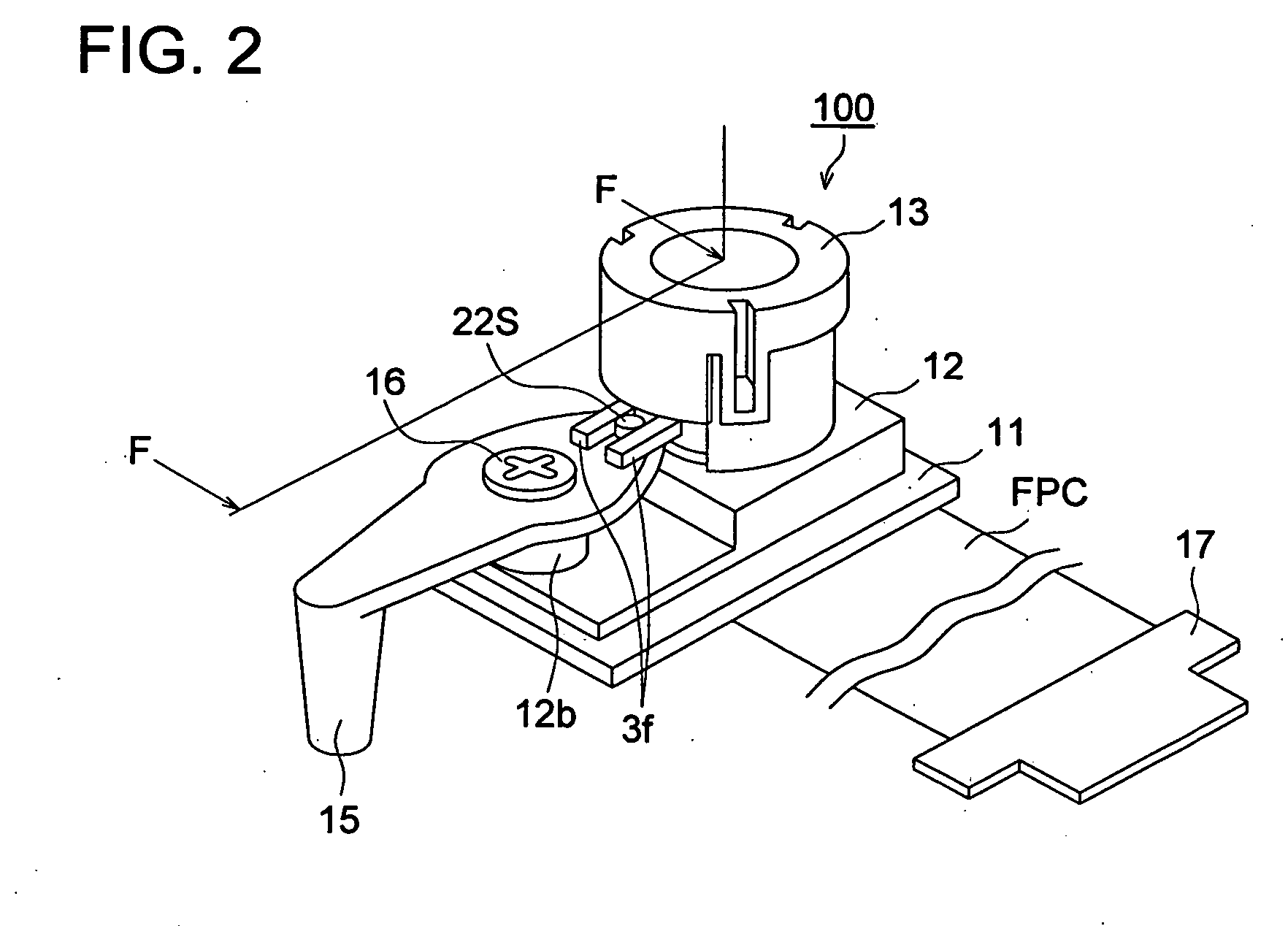
[0084]FIG. 2 is a perspective view of an image pickup device 100 in a first embodiment of the present invention. The image pickup device 100 in FIG. 2 is equivalent to the image pickup device S of FIG. 1.

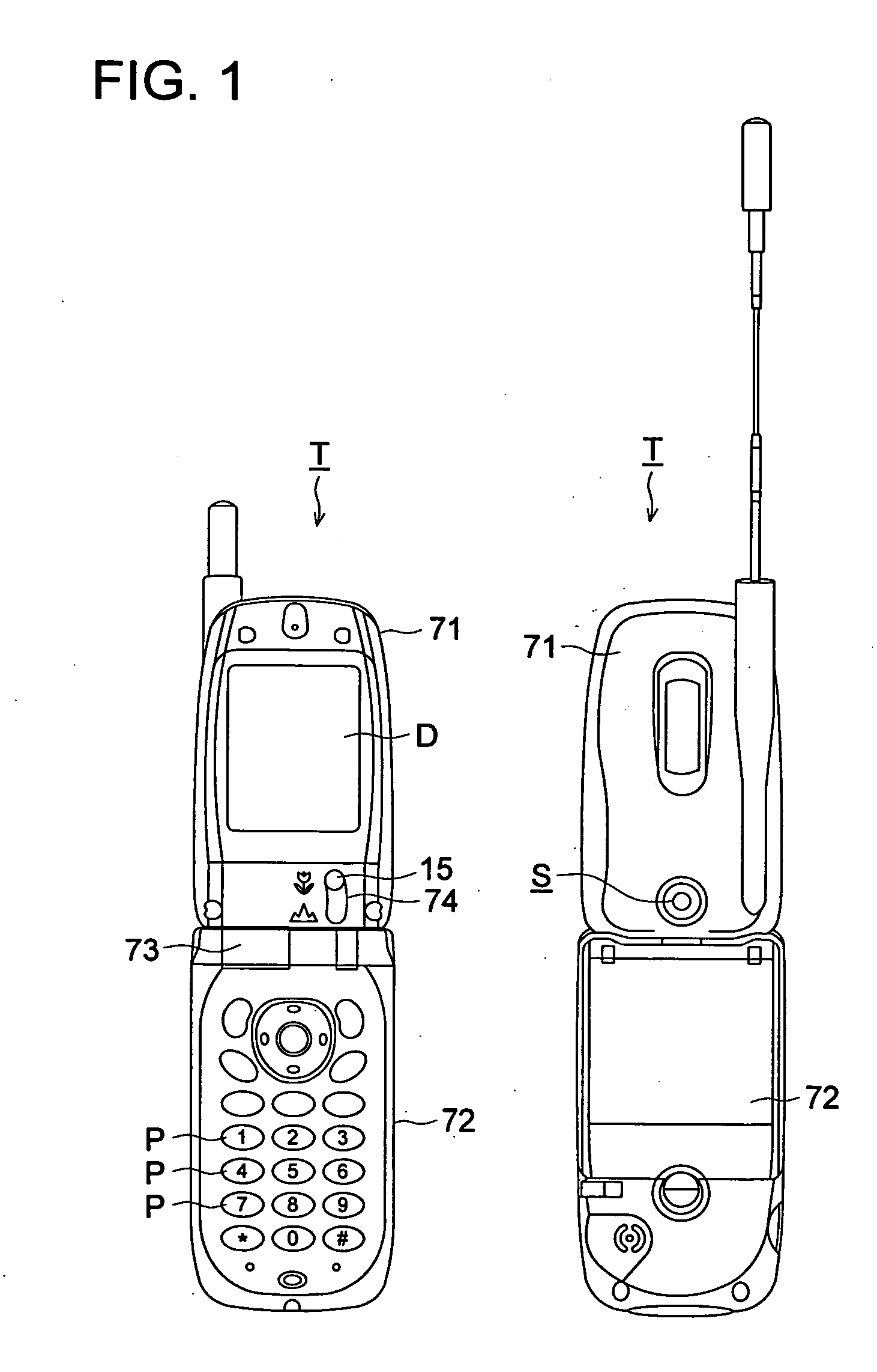
[0085] As shown in FIG. 2, the image pickup device 100 has an outer surface including: a printed circuit board 11 on which an image pickup element is mounted; a connector circuit board 17 for connection to any other control circuit board of a hand-held terminal having the image pickup device 100; a flexible printed cable (FPC) that connects the printed circuit board 11 and the connector circuit board 17; an outer frame member 12; a cover member 13 mounted on an upper face of the outer frame member 12; an operating member 15 that is pivotally installed on a boss 12b integrally formed on the outer frame member 12; and a shoulder screw 16 that pivotally secures the operating member 15.

[0086]FIG. 3(a) is a sectional view of the image pickup device 100, taken along line F-F of FIG. 2. ...

second embodiment

[0100] The following describes a second embodiment of the present invention. The second embodiment is an example in which a space at the photoelectric conversion side of an image pickup element is sealed using a mounting base and a part of an outer frame member.

[0101] An external view of a hand-held telephone T having an image pickup device 150 of the second embodiment, and a perspective view of this image pickup device are omitted from the description since both views are the same as those of FIGS. 1 and 2. Also, the image pickup device 150 below is equivalent to the image pickup device S of FIG. 1.

[0102]FIG. 5 is a sectional view of the image pickup device 150 according to the second embodiment of the present invention, the view being taken along line F-F of FIG. 2. In the description below, the same reference number or symbol is assigned to the same member in order to avoid duplication of the description. Also, only sections different from those of the first embodiment are desc...

third embodiment

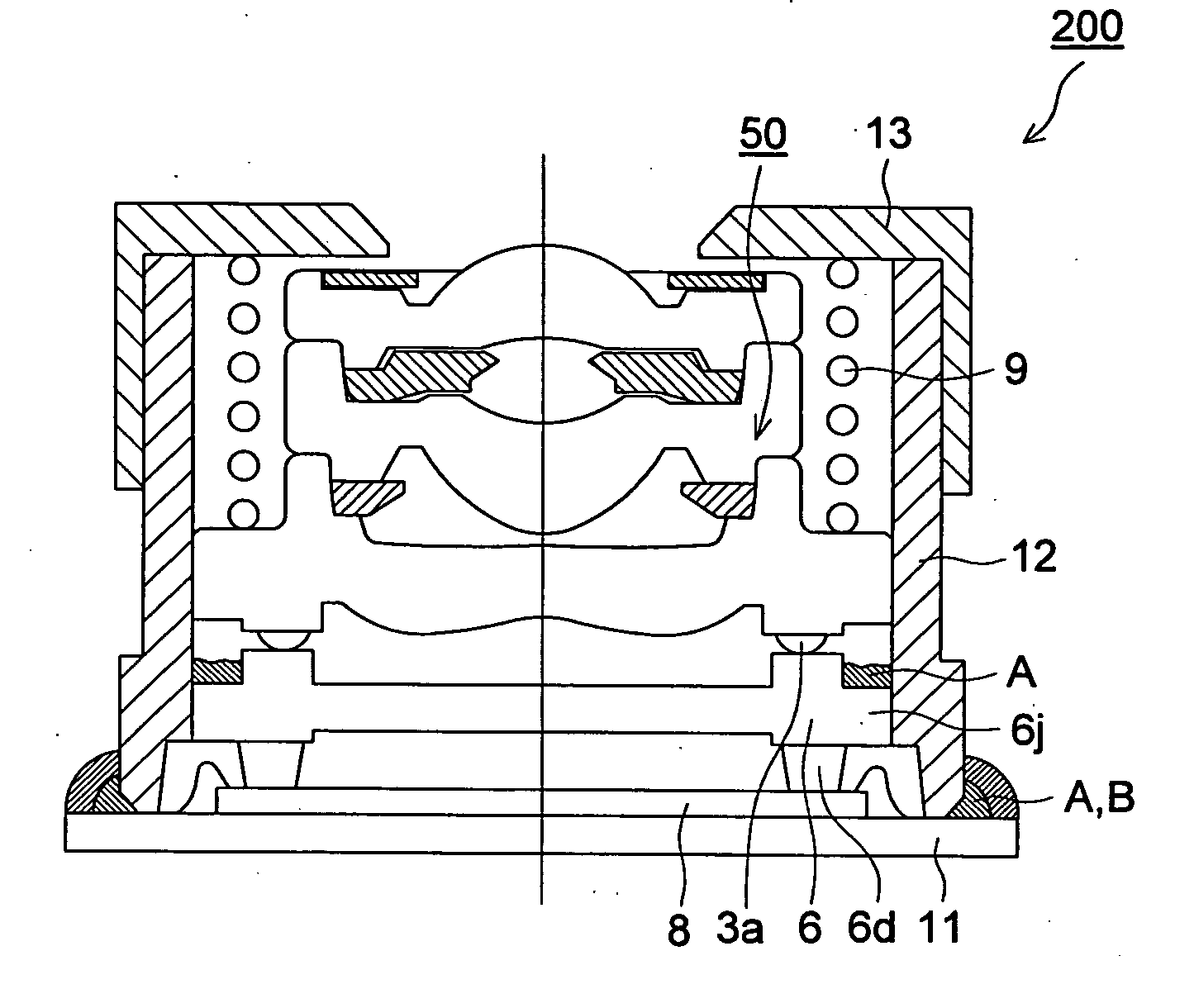
[0111] The following describes a third embodiment of the present invention. The third embodiment is an example in which a mounting base has horizontal abutting faces each formed with a different height and an image pickup optical system is assembled using either of the abutting faces selectively.

[0112] A hand-held telephone T with an image pickup device of the third embodiment has an appearance from which an opening 74 and an operating member 15 are omitted / deleted from the external view of FIG. 1. The image pickup device 200 below is equivalent to the image pickup device S of FIG. 1.

[0113]FIG. 7 is a perspective view of the image pickup device 200 according to the third embodiment of the present invention. In the description below, the same reference number or symbol is assigned to the same functional member in order to avoid duplication of the description. Also, only sections different from those of the above-described first and / or second embodiment are described in detail.

[011...


PUM


Abstract

This invention relates to dust-proof, moisture-proof structures of the image pickup devices mounted in small-size thin types of electronic apparatus. More specifically, an image pickup device of this invention includes an image pickup element, a mounting base having a formed leg section which abuts on the image pickup element, an image pickup optical system that guides photographic object light to the imaging region of the image pickup element, and an outer frame member that contains the image pickup element, the mounting base, and the image pickup optical system. The space formed at the photoelectric conversion plane side of the image pickup element is sealed by using the mounting base or by using the mounting base and a part of the outer frame member.

Description

FIELD OF THE INVENTION [0001] The present invention relates to image pickup devices, and more particularly to a compact and thin type of image pickup device built into a hand-held terminal, to an image pickup device capable of macro-photographing, and to a method of manufacturing these image pickup devices. BACKGROUND OF THE INVENTION [0002] Compact and thin types of image pickup devices are traditionally coming to be mounted in compact and thin types of electronic apparatus such as hand-held telephones and personal computers, and in PDAs (Personal Digital Assistants) and the like, to thereby enable transmission not only of voice information, but also of image information, to and from remote places. [0003] The image pickup devices mounted in these hand-held terminals are very short in the focal length of an image pickup optical system and have aperture F-numbers as small as about 2 to 4. For these reasons, the focal depth at the image side is very small and stringent accuracy is req...

Claims


Application Information

Patent Timeline
Patent Type & Authority Applications(United States)
IPC IPC(8): H04N5/225G02B27/00
CPCG02B27/0006H04N5/2253H04N5/2254H04N23/57H04N23/55H04N23/54
Inventor SAITO, MASASHISUGIURA, MUTSUMI
Owner KONICA MINOLTA OPTO
Why Eureka
Try Eureka