Stacker device

a technology of stacking device and paper clip, which is applied in the direction of thin material processing, article delivery, transportation and packaging, etc., can solve the problems of paper dropping in a curled state, paper with poor stacking characteristic generation, and poor stacking characteristic, so as to improve the operational efficiency of removing paper

Active Publication Date: 2010-12-14
PFU LTD
View PDF16 Cites 6 Cited by
  • Summary
  • Abstract
  • Description
  • Claims
  • Application Information

AI Technical Summary

Benefits of technology

[0011]It is therefore an object of the invention to provide a stacker device which is capable of controlling the stacking conditions optimally in correspondence with, for example, thin paper with weak stiffness, thick paper, and large- or small-sized paper, and of improving the operational efficiency in removing the paper.
[0012]It is also an object of the invention to provide a stacker device which is capable of improving the stacking characteristic of a large-sized medium and of rendering the device compact.
[0021]With this configuration, by virtue of the lifter which raises and lowers the first tray on which the paper is stacked, it becomes possible to optimize the stacking conditions in correspondence with, for example, thin paper with weak stiffness, thick paper, and large- or small-sized paper, and improve the operational efficiency in removing the paper.
[0023]In this case, it becomes possible to commonly use the paper transporting passage for both the discharged of the rejected paper and the discharge of the normal paper, thereby rendering the device compact.
[0027]In this case, it becomes possible to improve the stacking characteristic of a large-sized medium and render the device compact.

Problems solved by technology

With the related art, if the stacking depth becomes deep, since the stiffness is low particularly in the case of thin paper, there is a problem in that the leading end droops down, so that the paper drops in a curled state, and the stacking characteristic becomes very poor.
However since no consideration is given to the stacking positions corresponding to the types of paper, there is a problem in that paper with a poor stacking characteristic is generated.
Since there are many cases where the discharged paper tray is provided on an upper side of the device in conjunction with the trend toward a large-sized device, and an extension is extended to stack a large-sized medium, there is a problem in that the paper is very difficult to remove.
However, since the separate transporting passage is provided, there is a problem in that the device becomes large in size.

Method used


Image

  • Stacker device
  • Stacker device
  • Stacker device

Examples


Embodiment Construction

[0060]Referring to FIGS. 1 to 19, a description will be given of the best mode for carrying out the invention.

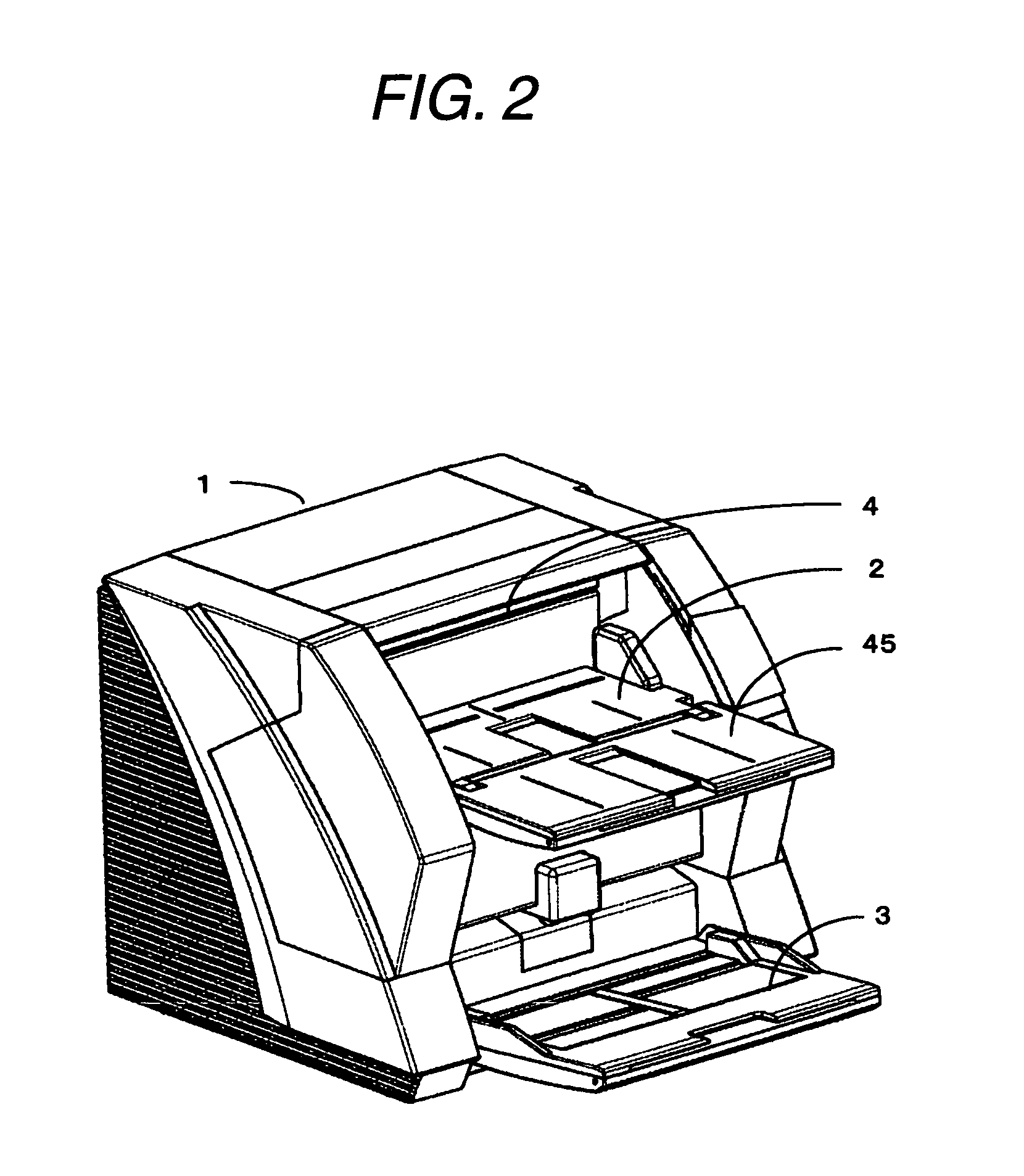
[0061]FIG. 2 is an external view of an image reading apparatus to which a stacker device in accordance with the invention is applied. In the drawing, in an image reading apparatus 1, a hopper device 3 for stacking document paper which is subject to reading and a stacker device 2 in which the document paper for which reading has been completed is stacked are disposed separately. A read head for reading characters, images, and the like on the document paper is disposed midway in a transport passage from the hopper device 3 to the stacker device 2. It should be noted that an extension tray 45 for stacking a large-sized medium is provided in the stacker device 2.

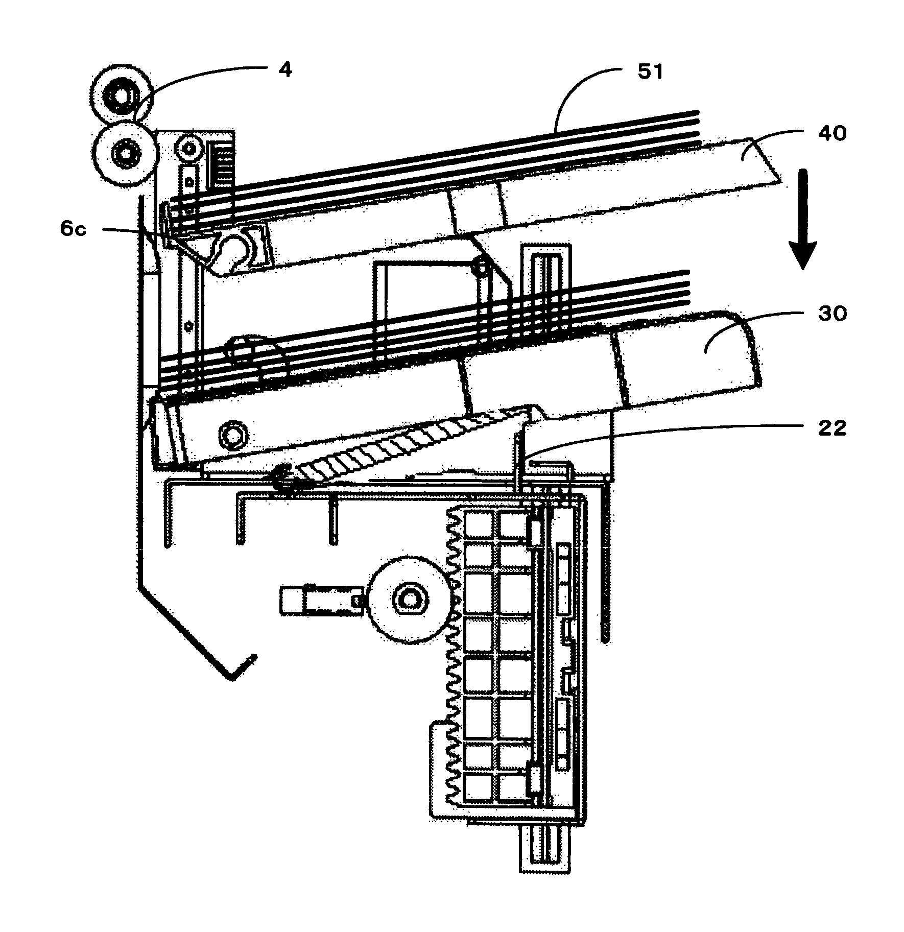
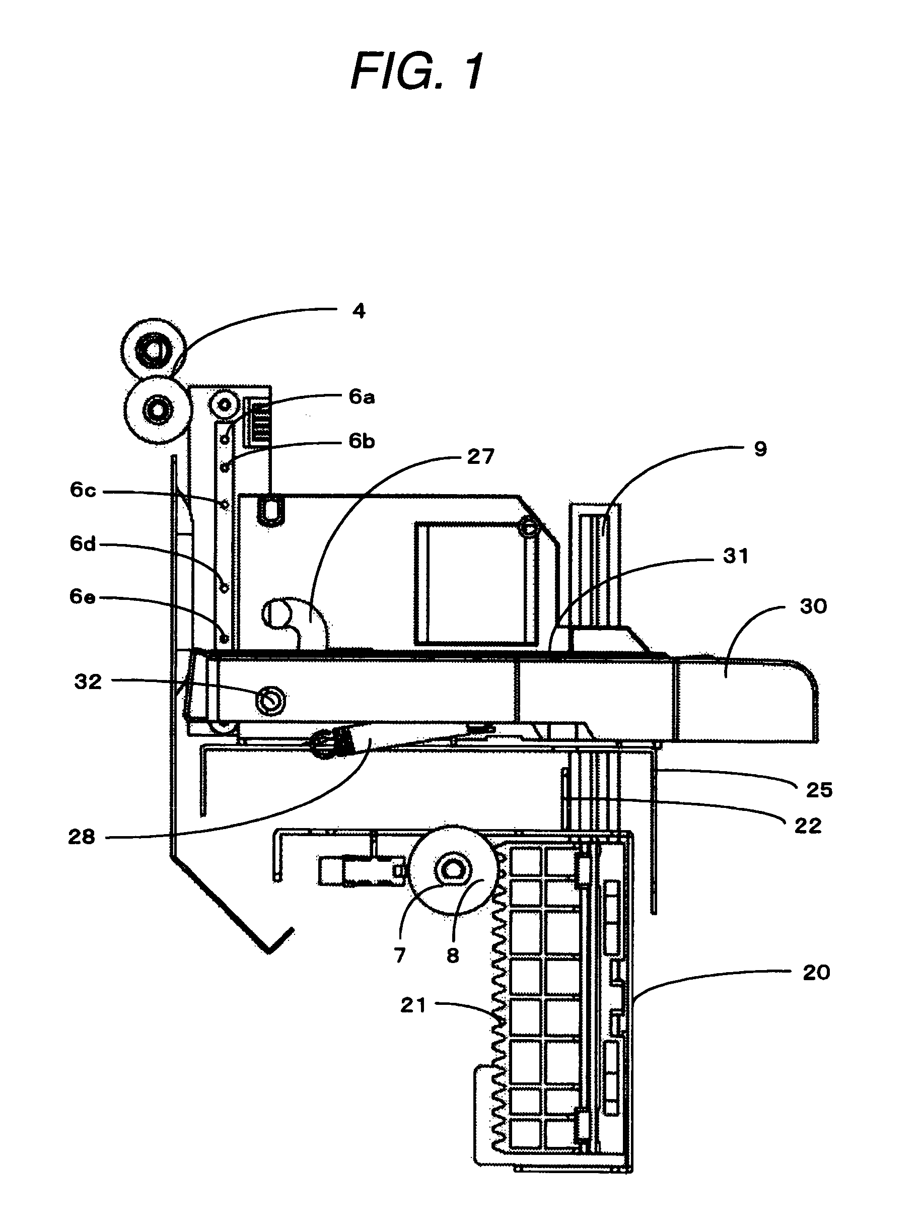
[0062]FIG. 1 is a diagram explaining the basic principle of the stacker device in accordance with the invention. FIG. 3 is an explanatory diagram of a main portion of the stacker device in accordance with the invention. ...


PUM


Abstract

A first tray is adapted to stack a paper discharged from a discharge port thereon. A lifter is operable to raise or lower the first tray. A detector is operable to detect a stacked state of the paper and the first tray. In a case where the paper is discharged onto the first tray, the first tray is raised or lowered based on the stacked state detected by the detector so as to keep a distance from the discharge port to an uppermost paper of the paper stacked on the first tray within a predetermined range.

Description

BACKGROUND OF THE INVENTION[0001]The present invention relates to a stacker device used in, for example, a sheet feed type image reading apparatus or the like, and more particularly to a stacker device provided with a lifting member for raising or lowering a tray.[0002]In a sheet feed type image reading apparatus, a hopper unit for stacking and accommodating paper or the like which is subject to reading and a stacker unit in which the paper or the like for which reading has been completed is stacked are generally disposed separately. A read head for reading characters, images, and the like on the paper or the like is disposed midway in a transport passage from the hopper unit to the stacker unit.[0003]There is a type of a stacker unit which includes a stacker in which the paper or the like for which reading has been completed properly is stacked and a reject stacker in which the paper or the like for which reading has not been completed properly is stacked. The paper or the like whi...

Claims


Application Information

Patent Timeline
Patent Type & Authority Patents(United States)
IPC IPC(8): B65H39/10
CPCB65H31/18B65H2801/39B65H2701/176B65H2405/1117B65H2405/11151B65H2405/11152
Inventor MATSUE, YASUHIRONAKAYAMA, TAKUMISHIKAN, MITSUHIRO
Owner PFU LTD
Why Eureka
Try Eureka