Check patentability & draft patents in minutes with Patsnap Eureka AI!

Connector assembly with a case and a dummy connector having a guide projection with a transverse protrusion

a technology of dummy connector and connector assembly, which is applied in the direction of live contact access prevention, coupling device connection, electrical apparatus, etc., can solve the problems of unfavorable interference of the protruding part with other components, and achieve the effect of preventing the erroneous insertion of the dummy connector

Active Publication Date: 2010-12-14
SUMITOMO WIRING SYST LTD
View PDF4 Cites 2 Cited by
  • Summary
  • Abstract
  • Description
  • Claims
  • Application Information

AI Technical Summary

Benefits of technology

Ensures correct orientation of dummy connectors during insertion, prevents forgotten insertion, and simplifies the design by allowing effective use of dead space for wire arrangement without interference issues.

Problems solved by technology

Further, the wires prevent only a projecting state of the protrusion from standing out and problems, such as the interference of the protrusion with other components, are unlikely.

Method used


Image

  • Connector assembly with a case and a dummy connector having a guide projection with a transverse protrusion
  • Connector assembly with a case and a dummy connector having a guide projection with a transverse protrusion
  • Connector assembly with a case and a dummy connector having a guide projection with a transverse protrusion

Examples


Embodiment Construction

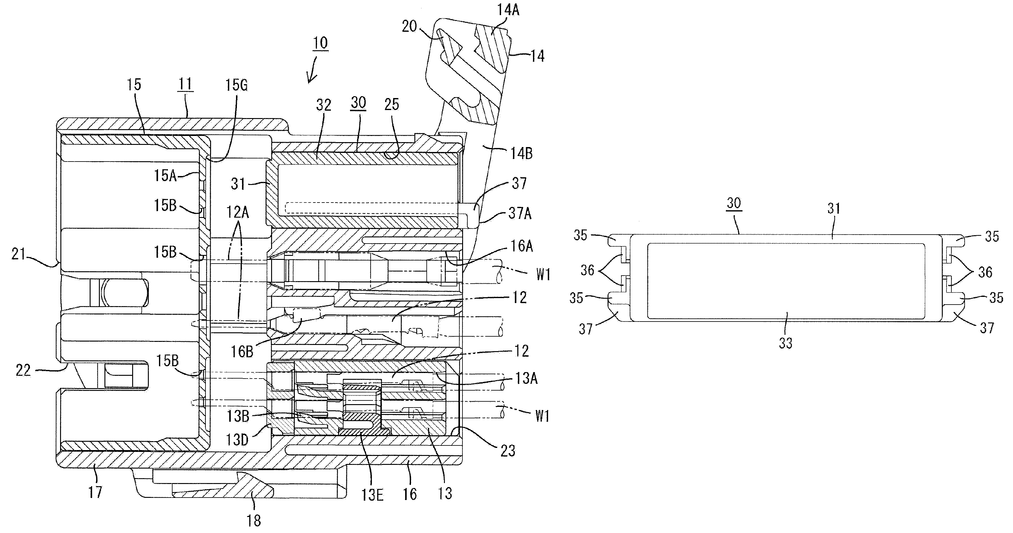
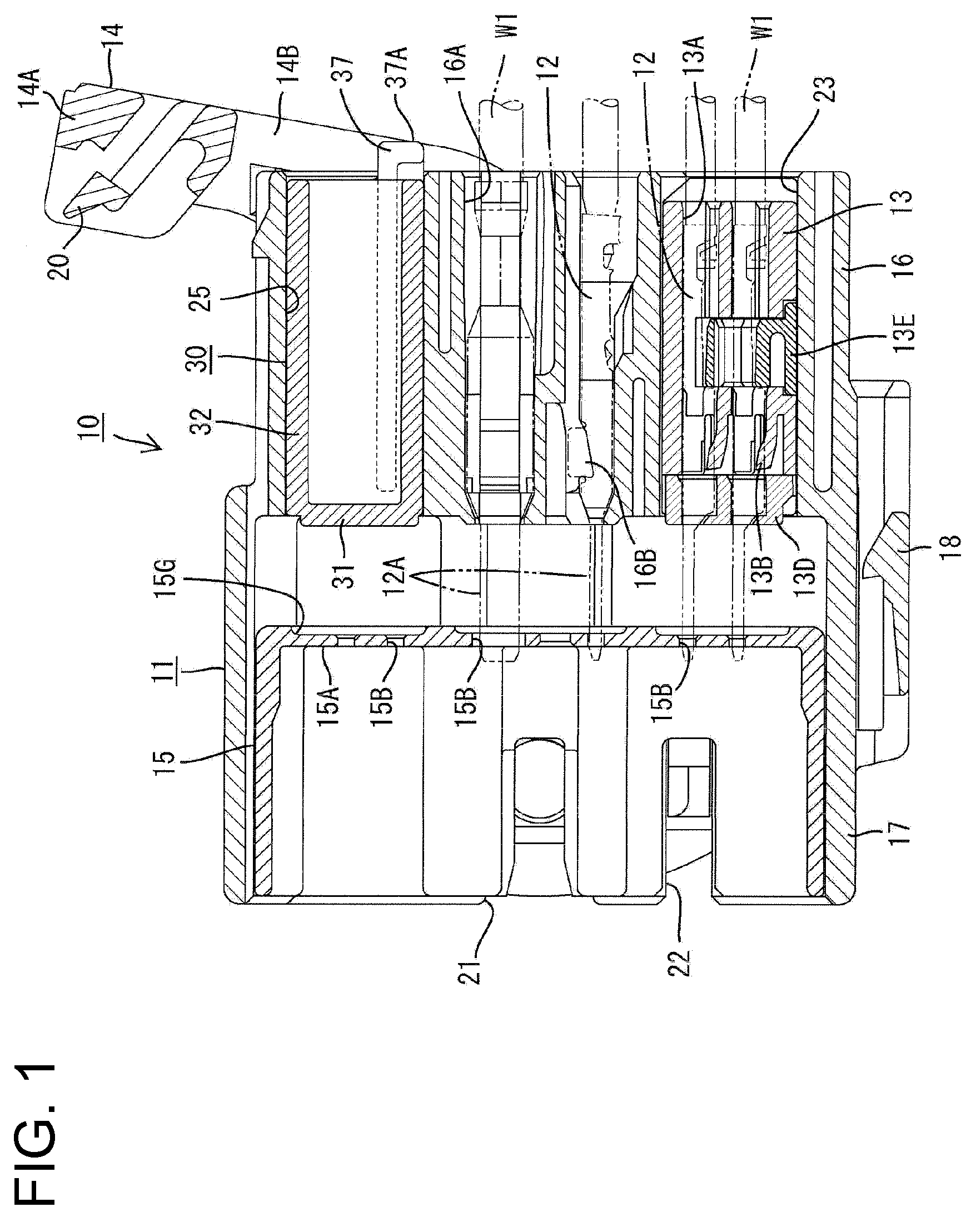
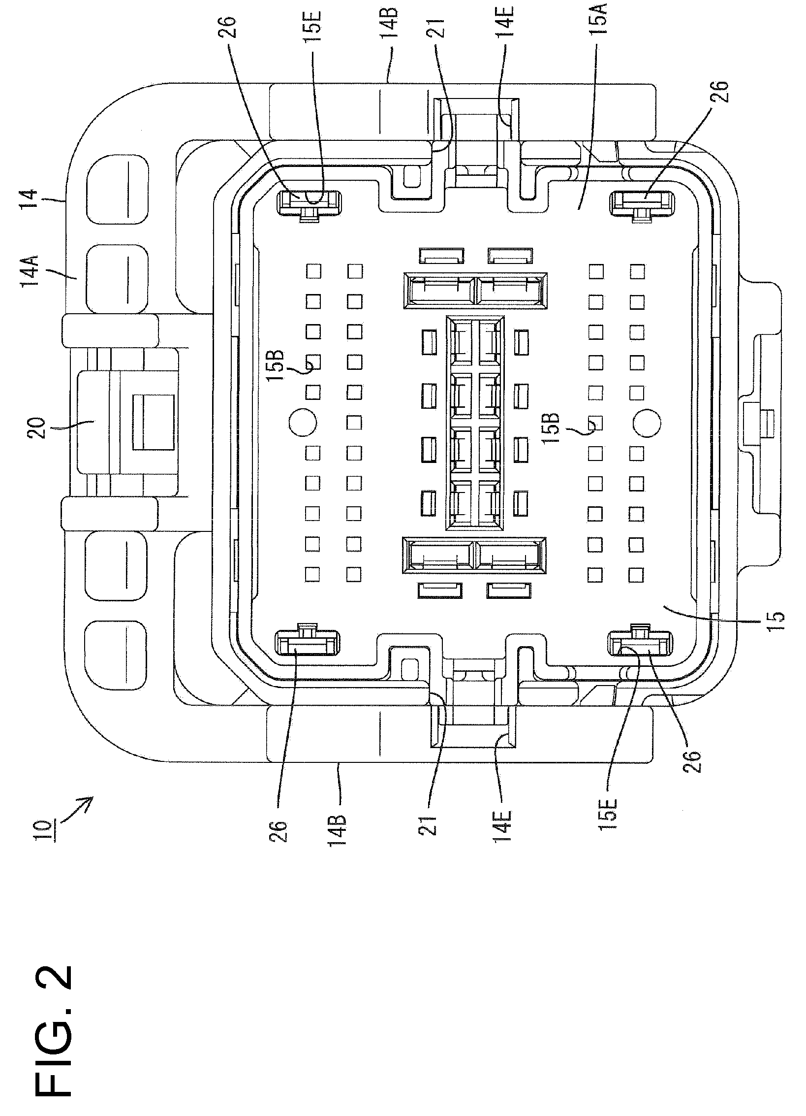
[0035]A connector assembly in accordance with the invention is illustrated in FIGS. 1 to 17. The connector assembly comprises male and female connectors 10, 50 connectable with each other. The male connector 10 includes a male housing 11, male terminal fittings 12, at least one male-side dummy connector 30, at least one male-side housing 13, a lever 14 and a moving plate 15. The female connector 50 includes a female housing 51, female terminal fittings 52, a female-side dummy connector 70 and a female-side housing part 53. In the following description, ends of the two connectors 10, 50 to be connected are referred to as front ends.

[0036]The male housing 11 is made e.g. of synthetic resin and includes block-shaped terminal accommodating portion 16 for accommodating the male terminal fittings 12 and a tubular receptacle 17 projecting forward from a peripheral edge of the front end of the terminal accommodating portion 16, as shown in FIG. 1. A mounting piece 18 projects back from the ...


PUM


Abstract

Male and female connectors (10, 50) include male and female housings (11, 51) with accommodating portions (25, 61) that have rear end insertion openings for accommodating dummy connectors (30, 70). The dummy connectors (30, 70) include protrusions (37, 78) that interfere with the opening edges of the accommodating portions (25, 61) and prevent insertion if the dummy connectors (30, 70) are reversed forward / backward. However, properly oriented dummy connectors (30, 70) can be inserted into the accommodating portions (25, 61) while leaving the protrusions (37, 70) projecting out from the insertion openings.

Description

BACKGROUND OF THE INVENTION[0001]1. Field of the Invention[0002]The invention relates to a connector.[0003]2. Description of the Related Art[0004]U.S. Patent Application Publication No. 2001 / 0024907 discloses a connector assembly with a dummy connector that is inserted into an accommodating portion of a case even though the dummy connector does not contribute to a circuit configuration. The dummy connector has a main body that closes an inner space of the accommodating portion to ensure a specified water resistance.[0005]No wire extends from the main body of the dummy connector and it is difficult to distinguish the front end from the rear end. Thus, the main body of the dummy connector may be reversed in forward / backward directions during insertion into the accommodating portion. In such cases, an operator may mistakenly believe that an inserting operation has been completed even though the dummy connector main body has been inserted only to an intermediate position. Additionally, ...

Claims


Application Information

Patent Timeline
Patent Type & Authority Patents(United States)
IPC IPC(8): H01R13/44
CPCH01R13/443H01R13/5213H01R13/62938
Inventor KOBAYASHI, YUKA
Owner SUMITOMO WIRING SYST LTD
Features
  • R&D
  • Intellectual Property
  • Life Sciences
  • Materials
  • Tech Scout
  • Unparalleled Data Quality
  • Higher Quality Content
  • 60% Fewer Hallucinations
Learn More