Device and method for manufacturing a three-dimensional object with a heated recoater for a building material in powder form

a three-dimensional object and recoater technology, applied in the field of recoaters, can solve the problems etc., and achieve the effects of reducing the control requirements of the heating device, reducing the pre-damage of the powder through cycles, and reducing the heating power required for the pre-heating layer already applied to the building area

Inactive Publication Date: 2010-12-14
EOS ELECTRO OPTICAL SYST
View PDF14 Cites 84 Cited by
  • Summary
  • Abstract
  • Description
  • Claims
  • Application Information

AI Technical Summary

Benefits of technology

The invention has several technical benefits. Firstly, it reduces the heating power required for powder preheating, which decreases the control requirements for the heating device and reduces pre-damage of the powder. Secondly, it ensures even heating of the powder material over the whole layer, which prevents overheating at the surface and avoids undesired thermal effects like the bimetal effect. Thirdly, it maintains constant thermal conditions in the powder bed by not dissipating heat energy from it through the recoater. Fourthly, it allows for fluidization and simultaneous preheating of the powder material using preheated gas. Lastly, it increases the contact surfaces for thermal contact between the powder material and the heated recoater by using a double blade with a reservoir chamber.

Problems solved by technology

The patent text describes a problem with current methods of manufacturing three-dimensional objects using powder layers. The problem is that the powder material can only be preheated if it has been applied to the building area, which prolongs the total building time. Additionally, there is uneven preheating of the powder layer due to the recoater moving across the building area. The patent text describes previous solutions, such as using a flexible wiper with a heating element for smoothing unevennesses of a liquid bath or compressing powder layers with a roller and heating it for transformation into a cohesive mass. The technical problem of the patent text is to provide a solution for preheating powder layers evenly and efficiently in a three-dimensional object manufacturing process.

Method used


Image

  • Device and method for manufacturing a three-dimensional object with a heated recoater for a building material in powder form
  • Device and method for manufacturing a three-dimensional object with a heated recoater for a building material in powder form
  • Device and method for manufacturing a three-dimensional object with a heated recoater for a building material in powder form

Examples


first embodiment

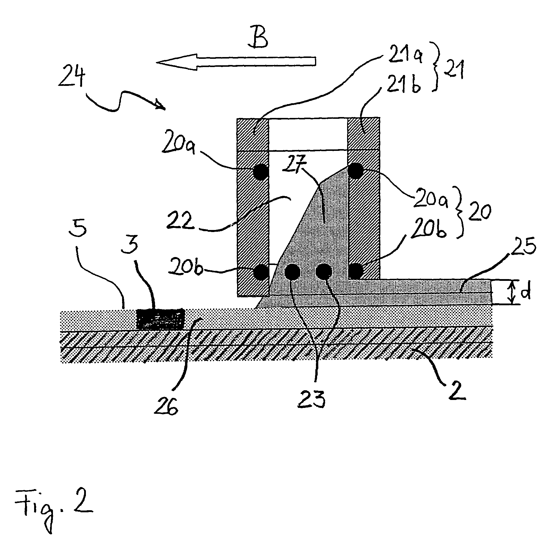
[0026]FIG. 2 shows the recoater 24 used in the device for the manufacturing of a three-dimensional object according to the invention, which serves for the applying of layers of a powder material.

[0027]The recoater 24 according to a first embodiment is designed as a double blade 21 consisting of two rigid blades 21a and 21b, which are laterally held together by two side walls which are not shown. The two rigid blades 21a and 21b are thereby formed of a rigid material, in particular of metal, a heat resistant plastics or of a ceramics. The two blades and the two side walls form a reservoir chamber 22 being open to the top and to the bottom, which serves for receiving the powder material for one layer.

[0028]The recoater heater 20 is integrated in the blades 21a and 21b. The heating of the recoater consists of two heating wires 20a and 20b extending in the inside of the blades 21a and 21b. Further a grid of heating wires 23 is arranged at the lower end of the reservoir chamber 22 which ...

second embodiment

[0035]FIG. 3 shows the recoater 30 used in the device for the manufacturing of a three-dimensional object according to the invention.

[0036]The recoater 30 is designed in the form of a rigid blade 34. Thereby, the rigid blade 34 is formed from a rigid material, in particular from a metal, a heat resistant plastics or a ceramics. In the blade 34 a recoater heater in form of a heating wire 31 is integrated. As in the first embodiment, the recoater 31 is moveable through a drive indicated by the arrow B to and fro between two end positions across the building area. The recoater according to the second embodiment differs from the recoater 24 according to the first embodiment in that the powder reservoir 32 for applying a layer is not enclosed in a reservoir chamber 22 between two blades but is moved by one of the blades during applying of the layer 25 in front of the same. During applying the layer 25, the powder reservoir 32 is in thermal contact with the blade, in particular with the l...

third embodiment

[0037]FIG. 4 shows the recoater 40 used in the device for the manufacturing of the three-dimensional object according to the invention.

[0038]The recoater 40 according to the third embodiment is like the recoater 20 according to the first embodiment designed as double blade 42 of two rigid blades 41a and 41b which are rigidly connected to each other. Thereby, the two rigid blades 41a and 41b are made from a rigid material, in particular from metal, a heat resisting plastics or from a ceramics. A fluidizing device is integrated into the blades 41a and 41b, respectively, which consists of an antechamber 42 and a fluidizing plate 43. To let in nitrogen into the antechamber 42, a supply 44 with a valve 45 is provided. The fluidizing plate 43 comprises many small openings, the diameter of which is smaller than the diameter of the grains of the powder material so that the nitrogen gas can exit through the fluidizing plate 43 from the antechamber 42, but powder material 47 cannot reach the ...


PUM

PropertyMeasurementUnit
Temperatureaaaaaaaaaa
Timeaaaaaaaaaa
Areaaaaaaaaaaa

Abstract

A device and a method for the manufacturing of a three-dimensional object (3) by solidifying of layers (25, 26) of a powder material at locations corresponding to the respective cross-section of the object (3) is provided. The device comprises a recoater (24) for applying the layers of the powder material (27) in the building area (5) which is moveable across the building area (5). The recoater (24) is designed with a rigid blade (21a, 21b) which is rigidly connected to the recoater (24). For preheating the powder material (27), the recoater (24) is provided with a heating device (20, 23) which is at least partially integrated into the recoater. In this way it is possible to preheat the powder already during or prior to applying it as a layer and thereby shortening the whole building time for the three-dimensional object (3).

Description


Claims


Application Information

Patent Timeline
Owner EOS ELECTRO OPTICAL SYST
Why Eureka
Try Eureka