Flush mount-corner mount gang box

a gang box and flush mount technology, applied in the direction of substation/switching arrangement casings, filing appliances, coupling device connections, etc., can solve the problems of drywall construction not being completed, wire may be moved by the worker applying drywall, lost behind the drywall,

Inactive Publication Date: 2010-12-28
HONEYWELL INT INC
View PDF6 Cites 5 Cited by
  • Summary
  • Abstract
  • Description
  • Claims
  • Application Information

AI Technical Summary

Problems solved by technology

A typical problem with installation of electronic devices including, for example, alarm systems or security systems including detectors, during construction of a building, whether commercial or residential, relates to running and placing a wire in a corner between wall frames during pre-wirings.
The workers move the wire because the drywall construction cannot be completed to specification, i.e., a corner with abutting drywall having joint compound and tape ready for primer and painting, with the wire and nail protruding from the frame.
For example, the wire may be moved by the worker applying drywall, or lost behind the drywall, or erroneously cut.
If the wire is moved to another location, for example, hung on another stud for the flat surface of the wall instead of the corner, the wire may be included in a junction box in the wall and the device, when installed, will not be in the correct location.
Further, when an installation wire is moved or cut, the installer must spend time to relocate or rewire, which increases labor costs.
Attempts to fasten a wire and detector to the beams or studs once drywall is in place may require trial and error and may cause damage to the drywall which would need to be repaired.
A further disadvantage of attaching a device in a corner once drywall is in place includes the need for multiple screws or the like to mount a device such as a detector through the drywall opening the opportunity for damage to the drywall and the need to cover screw heads.
Further, mounting the detector to the drywall itself is not as stable as mounting to a beam and also may damage the drywall and require repair.

Method used


Image

  • Flush mount-corner mount gang box
  • Flush mount-corner mount gang box
  • Flush mount-corner mount gang box

Examples


Embodiment Construction

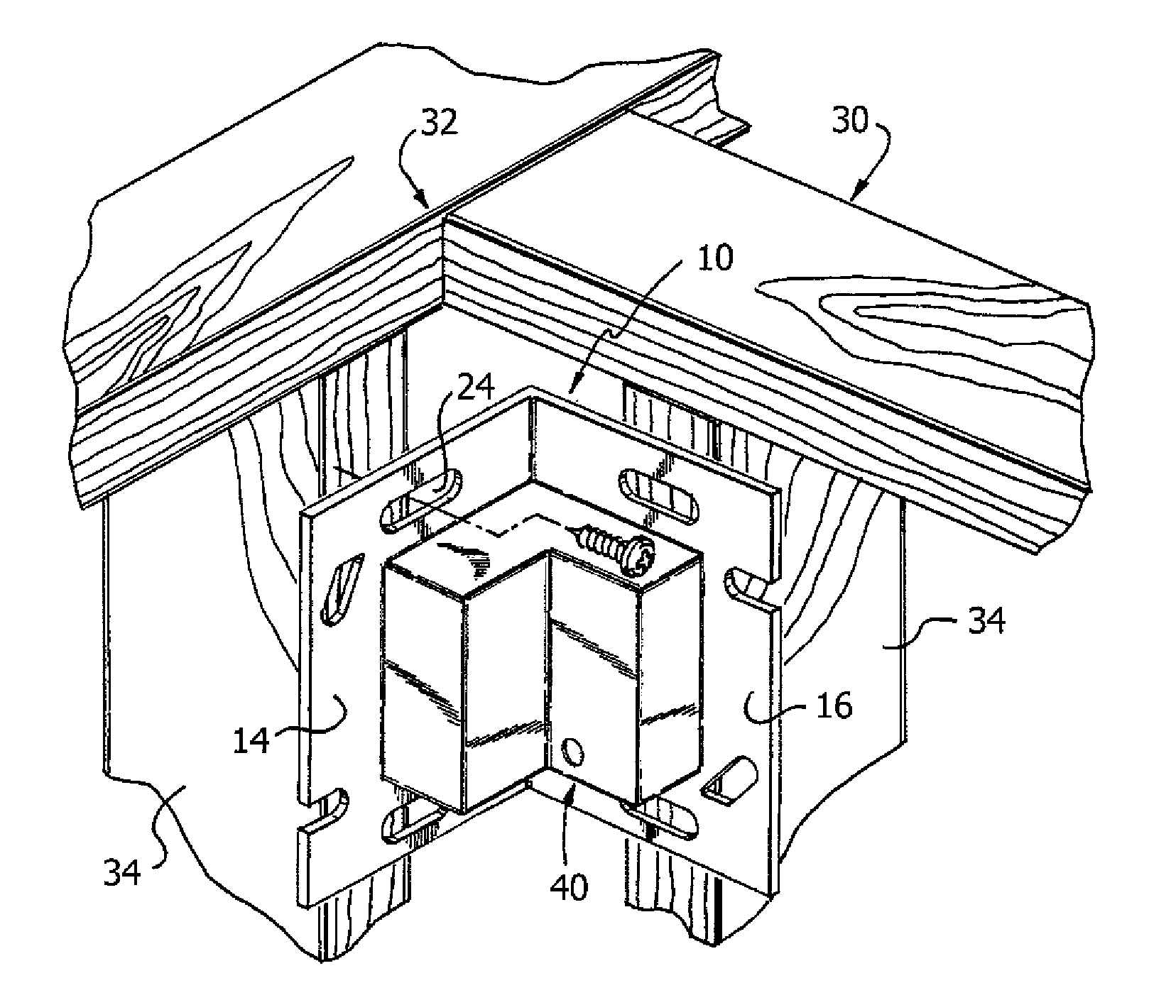
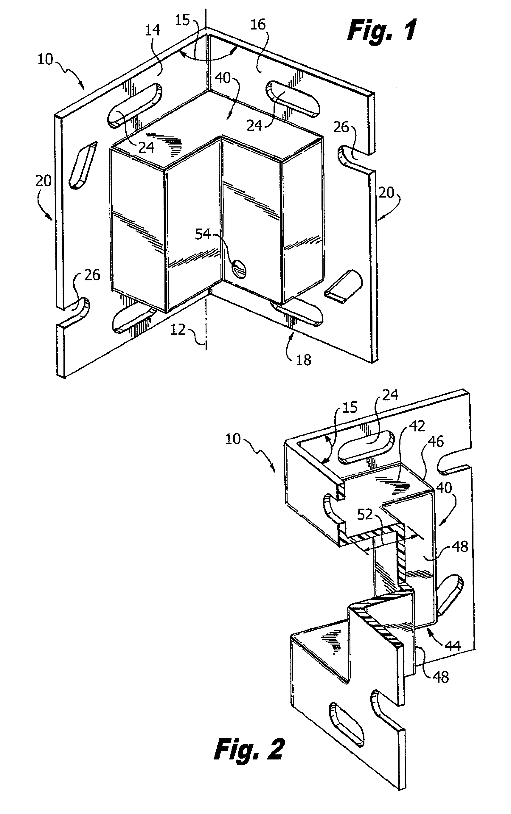
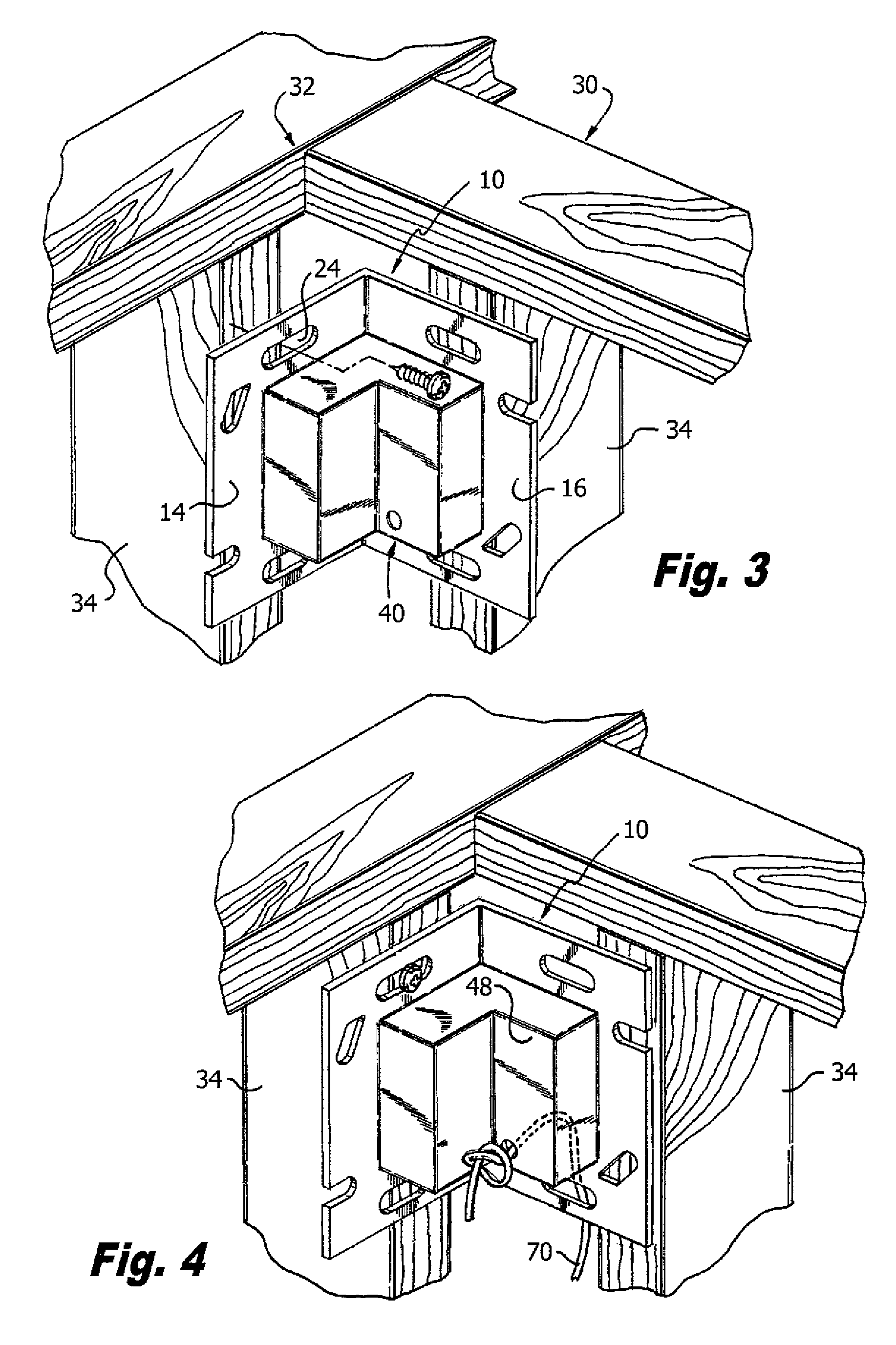
[0021]Referring to FIGS. 1 and 2, an illustrative embodiment according to the present invention of a housing 10 for hanging a wire 70 (shown in FIG. 4) in a corner defined by wall frames. The housing 10 may also be referred to as a box or a corner mounted gang box. The housing 10 includes an angular back plate 14 having top 16, bottom 18, and opposite side edges 20. The back plate 14 includes holes 24 and slots 26 for mounting the back plate to a building wall frame 30, shown in FIG. 3. The building wall frame 30 includes a corner 32 defined by studs, for example, wood studs 34 shown in FIGS. 3 and 4.

[0022]The angular back plate 14 is bifurcated at an acute angle 15 about an axis 12, which in the embodiment of the invention shown in FIGS. 1 and 2, is ninety degrees. However, the back plate can also be divided at other angles. The housing 10 further includes an angular raised portion 40 integral with the back plate 14. The angular raised portion 40 may be molded together with the bac...


PUM

PropertyMeasurementUnit
acute angleaaaaaaaaaa

Abstract

The present invention includes a housing for hanging or mounting a wire and a device in a corner between two walls of a building. The housing includes an angular back plate. The angular back plate is bifurcated at an acute angle and the backplate further includes an angular raised portion which is similarly bifurcated at an acute angle and positioned in mating relation with the angular back plate. The raised portion is recessed from top, bottom and side edges of the angular back plate. The raised portion has planar front portions in angular relation to each other and enclosing the raised portion. The back plate is mounted to a corner defined by the wall frames using back plate holes. The angular raised portion mates with a building material affixed to the building wall frame. One of the planar front portions of the angular raised portion defines a hole for passing the wire therethrough.

Description

FIELD OF THE INVENTION[0001]The present invention relates to housings, electrical junction boxes and gang boxes for used in construction, and more particularly, a housing and method for hanging electrical wires in a wall corner during building construction.BACKGROUND OF THE INVENTION[0002]Currently during building construction, a housing such as an electrical junction box or gang box is positioned in a wall, usually attached to a stud, before further construction of the wall, e.g., attaching drywall to the frame. Such boxes house and mount, for example, electric outlets and switches, and are positioned in the wall frame on a beam or stud during pre-construction, i.e., before dry walling. A typical problem with installation of electronic devices including, for example, alarm systems or security systems including detectors, during construction of a building, whether commercial or residential, relates to running and placing a wire in a corner between wall frames during pre-wirings. The...

Claims


Application Information

Patent Timeline
Patent Type & Authority Patents(United States)
IPC IPC(8): H01H9/02
CPCH02G3/123Y10T29/49826
Inventor GARAVUSO, MICHAELDODD, JAMES MICHAELBABICH, TOM
Owner HONEYWELL INT INC
Why Eureka
Try Eureka