Multifunctional control channel for pseudowire emulation

a multi-functional control and pseudowire technology, applied in the field of multi-functional control channels for pseudowire emulation, can solve the problems of increasing the operational cost of pwe-based services and channel may only serv

Active Publication Date: 2010-12-28
VERIZON PATENT & LICENSING INC
View PDF3 Cites 4 Cited by
  • Summary
  • Abstract
  • Description
  • Claims
  • Application Information

AI Technical Summary

Problems solved by technology

However, each control channel may only serve specific functions for which it is established.
To apply different types of control functions, the pseudowires may need to be re-established, which, in turn, can lead to downtime and increased operational cost of PWE-based services.

Method used


Image

  • Multifunctional control channel for pseudowire emulation
  • Multifunctional control channel for pseudowire emulation
  • Multifunctional control channel for pseudowire emulation

Examples


Embodiment Construction

[0025]The following detailed description refers to the accompanying drawings. The same reference numbers in different drawings may identify the same or similar elements. As used herein, the term “bidirectional forwarding detection” (BFD) may refer to continuous monitoring of a route or a data path for faults in both forward and reverse directions.

[0026]Implementations described herein may relate to establishment and / or use of a multifunctional control channel for sending control messages through pseudowires. A multifunctional control channel may serve many functions without re-establishing the pseudowire.

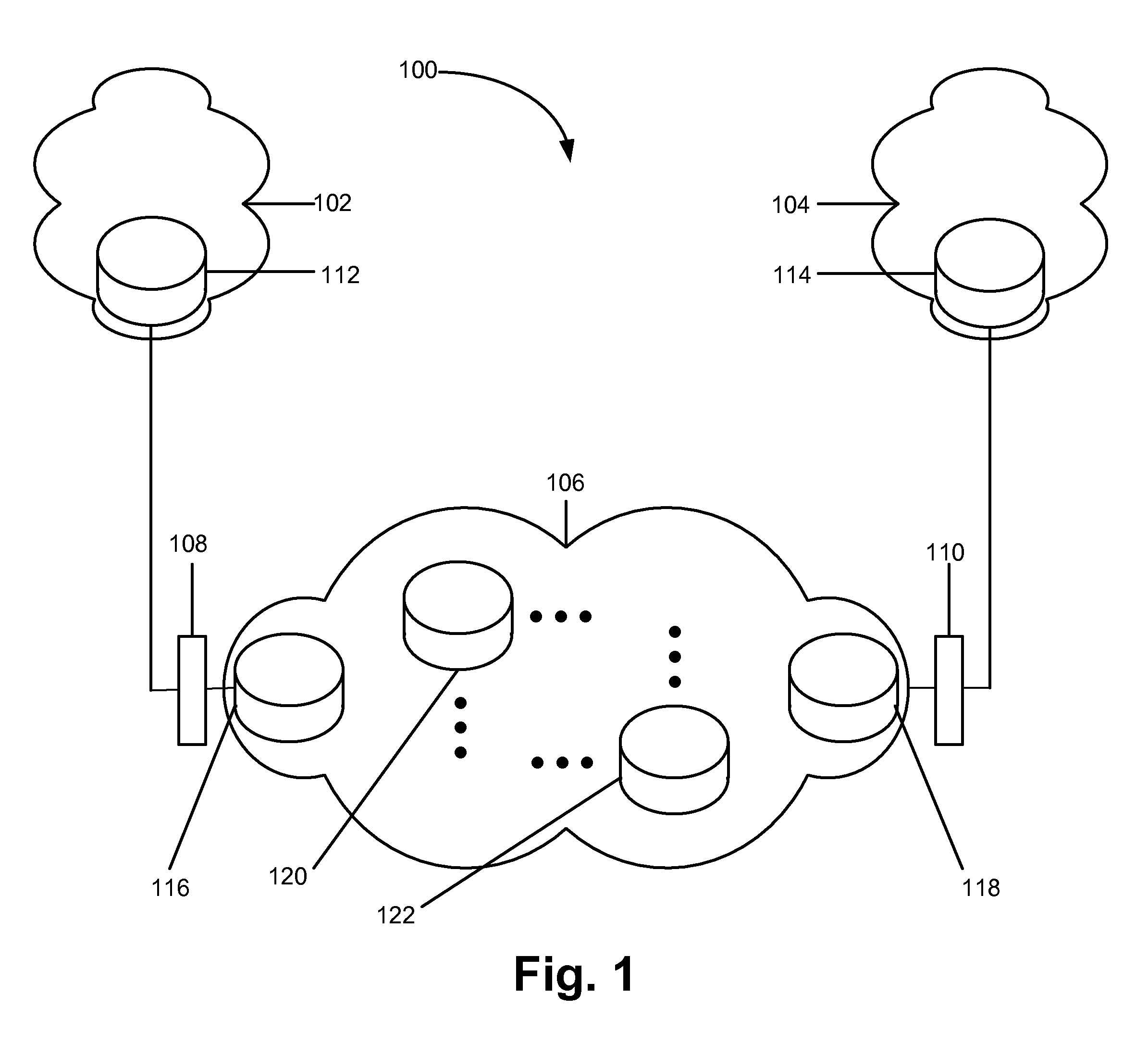
[0027]FIG. 1 shows, at a data link layer level (i.e., layer 2 in the Open Systems Interconnection (OSI) network model), a network 100 in which a multifunctional control channel may be implemented. Network 100 may include legacy networks 102 and 104, an IP / MPLS network 106, and attachment circuits 108 and 110.

[0028]Legacy networks 102 and 104 may include devices and / or systems for pr...


PUM


Abstract

A system advertises a multifunctional control channel (MFCC) in an interface parameter sub-type-length-value (TLV) of an advertisement label mapping message that is dispatched to a network device. The system also processes a reply label mapping message that is transmitted from the network device in response to the advertisement label mapping message and updates a label information base to establish a pseudowire and a MFCC associated with the pseudowire.

Description

RELATED APPLICATION[0001]This application claims priority under 35 U.S.C. §119 based on U.S. Provisional Patent Application No. 60 / 871,209, filed Dec. 21, 2006, the disclosure of which is incorporated by reference herein in its entirety.BACKGROUND INFORMATION[0002]Legacy network systems, such as ones based on Frame Relay or Asynchronous Transfer Mode (ATM), may communicate with packet switched networks (PSN), such as an Internet Protocol (IP) switching network or a Multi-protocol Label Switching (MPLS) network, which provide pseudowire emulation (PWE). PWE and associated pseudowires may be managed and controlled by establishing and using control channels for the pseudowires.[0003]However, each control channel may only serve specific functions for which it is established. To apply different types of control functions, the pseudowires may need to be re-established, which, in turn, can lead to downtime and increased operational cost of PWE-based services.BRIEF DESCRIPTION OF THE DRAWIN...

Claims


Application Information

Patent Timeline
Patent Type & Authority Patents(United States)
IPC IPC(8): H04J1/16H04L12/56
CPCH04L12/66H04L45/10H04L45/507H04L45/68
Inventor KRZANOWSKI, ROMAN
Owner VERIZON PATENT & LICENSING INC
Why Eureka
Try Eureka