
ATR-probe

a total reflection and probe technology, applied in the field of atrprobes, can solve the problems of reducing the effectiveness of coupling, consuming a large volume of material, requiring many facets, and complex optical designs, and achieve the effect of preventing or reducing interference between the end face and the second surfa

Active Publication Date: 2010-12-28
ENDRESS HAUSER CONDUCTA GESELLSCHAFT FUER MESS UND REGELTECHNIK MBH CO KG
View PDF9 Cites 1 Cited by
  • Summary
  • Abstract
  • Description
  • Claims
  • Application Information

AI Technical Summary

Benefits of technology

"The present invention provides an improved ATR-probe that overcomes the limitations of previous designs. The ATR-probe includes a housing with an inner space and a transparent radiation guiding body closing the media opening. The housing has a support body extending out of the inner space. The ATR-probe also includes transmission light conductors and receiving light conductors that extend in the inner space. The light from the media opening is guided through the media opening and the sensitive section of the housing, and then out of the housing through the media opening. The light is guided through total reflection in the radiation guiding body and is coupled out through the receiving light conductors. The effective area of the transmission light conductors is smaller than the effective area of the receiving light conductors. The first and second surfaces of the radiation guiding body are positioned and oriented in such a way that interference between the surfaces is reduced. The support body can include a ferrule and a separation between the end faces of the light conductors and the second surface of the radiation guiding body is set. The ATR-probe can also include a dispersive element or gratings as a dispersive element or an interferometer. The second surface extends to the outer edge of the radiation guiding body."

Problems solved by technology

A challenge for the design of these probes is presented by the in- and out-coupling of the light into and out of the radiation guiding body, for, in the ideal case, each ray should, on the one hand, undergo a number of total reflections at the bounding surface in contact with the medium, and, on the other hand, the construction should be simple.
Here, however, there is the problem of the in-coupling.
Due to the high material price, however, complex optical designs, which consume a large volume of material, or require many facets, are too expensive.
This construction is, however, very complicated, since the interface between the coupling body and the radiation guiding body is susceptible to disturbances, for example, on the basis of pressure- and temperature fluctuations, which can strongly degrade the effectiveness of the coupling.

Method used


Image

  • ATR-probe
  • ATR-probe
  • ATR-probe

Examples


Embodiment Construction

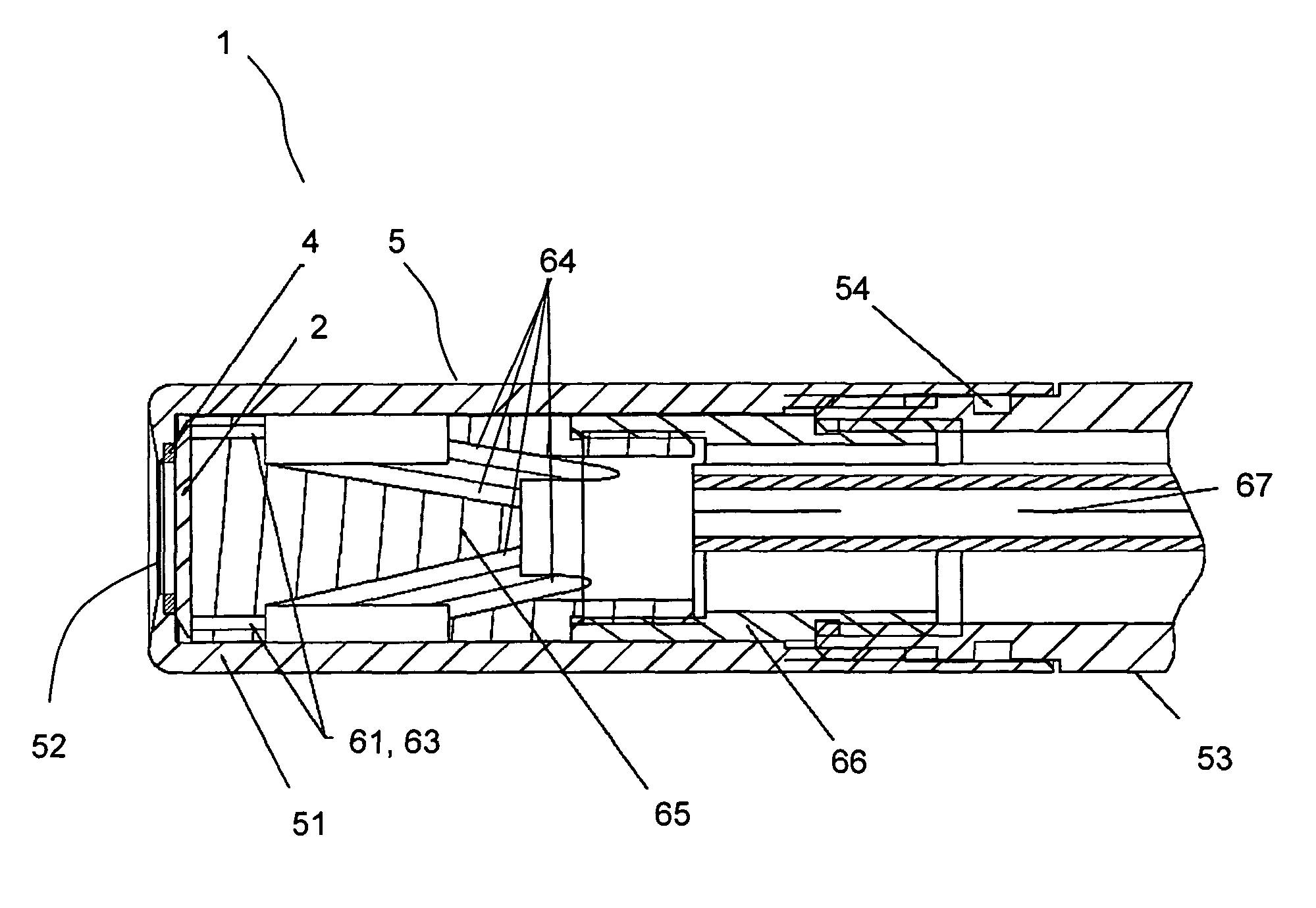
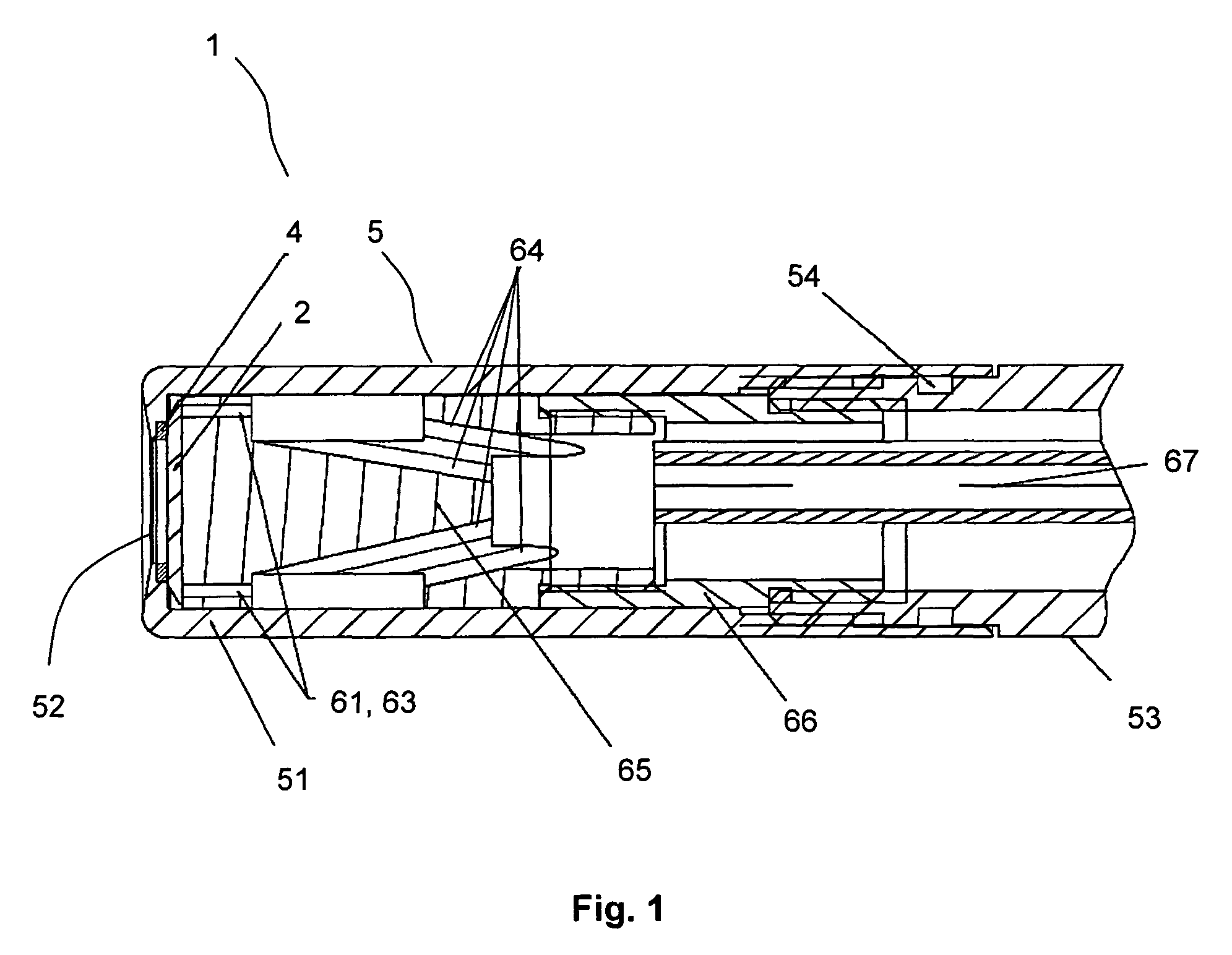
[0031]Construction of an ATR-probe of the invention is presented in longitudinal section in FIG. 1. Provided as radiation guiding body 2 is a diamond-element having planparallel surfaces. Radiation guiding body 2 is axially held, with interpositioning of an elastic sealing ring 4 (especially in the form a gasket), against a peripheral sealing surface around a frontal opening 52 in a cylindrical probe housing 5. Through the frontal opening 52, a section of a first planparallel surface of the radiation guiding body 2 can be contacted with a medium to be measured. The sealing ring 4 can comprise, in principle, any media resistant (especially relative to acids, bases and solvents), as well as pressure- and temperature-resistant materials. Currently, Kalrez elastomer is preferred.

[0032]The probe housing includes a probe head 51, which has, on its frontal end face, the frontal opening 52. To the rear, the probe head is adjoined by a probe shaft tube 53, which engages in the probe head, wh...


PUM


Abstract

An ATR-probe including: a housing having a media opening; a radiation guiding body closing the media opening and having two planparallel surfaces, between which light can be guided by means of total reflection. A section of a first planparallel surface bordered by a sealing ring can be contacted through the media opening with a medium to be measured. Transmission light conductors and receiving light conductors in the housing, wherein light is guided from the transmission light conductors, through the radiation guiding body, into the receiving light conductors; and wherein adjoining the first planparallel surface are first and second deflection surfaces, on which, respectively, light coupled into the radiation guiding body and light to be coupled out are deflected by total reflection, so that the light can be guided between the planparallel surfaces by means of total reflection. The light is not collimated, and the effective area of the transmission light conductors is smaller than the effective area of the receiving light conductors.

Description

TECHNICAL FIELD[0001]The present invention relates to an ATR-probe (Attenuated Total Reflection Probe) for examining aqueous or liquid media.BACKGROUND DISCUSSION[0002]ATR-probes include, usually, a radiation guiding body, in which light is guided by means of total reflection at a surface of the body, wherein the surface is contactable with the medium to be examined, whereby the evanescent field of the light interacts with the medium.[0003]The radiation guiding body is usually arranged at a media opening of a probe housing, which it closes, and through which a surface of the radiation guiding body is contactable with the medium.[0004]A probe includes, furthermore, a light source for coupling light into the radiation guiding body and a detector for transducing the light coupled out of the radiation guiding body into an electrical signal, as well as, should the application require, light conductors for conducting light from the light source to the radiation guiding body or from the la...

Claims


Application Information

Patent Timeline
Patent Type & Authority Patents(United States)
IPC IPC(8): G02B6/00
CPCG01N21/552
Inventor MIKKELSEN, HAKONMÜLLER, ANDREASHENZI, PATRIC
Owner ENDRESS HAUSER CONDUCTA GESELLSCHAFT FUER MESS UND REGELTECHNIK MBH CO KG
Learn More