Controlled collar vacuum

a vacuum and control collar technology, applied in the field of milking machines, can solve the problems of not all udder quarters finish milking simultaneously, bad treatment of these teats, etc., and achieve the effects of reducing over-milking, improving the utilization of milking equipment, and reducing milking times

Active Publication Date: 2011-01-04
DELAVAL HLDG AB
View PDF17 Cites 5 Cited by
  • Summary
  • Abstract
  • Description
  • Claims
  • Application Information

AI Technical Summary

Benefits of technology

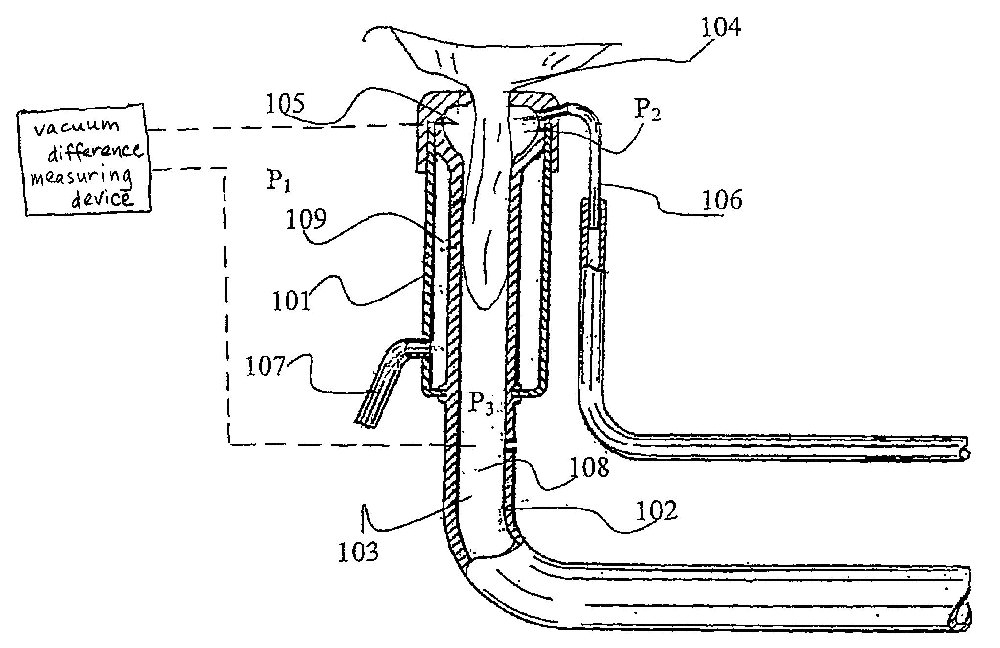
[0013]The present inventor has discovered that the difference between the two vacuum levels P2 and P3 to a very large extent determines how fast the milking will be performed. Thus, by varying the vacuum level P2 in the space, the milking time for an individual teat can be controlled. This can in turn be used in a number of different ways to achieve an optimal milking procedure, as will be described below.
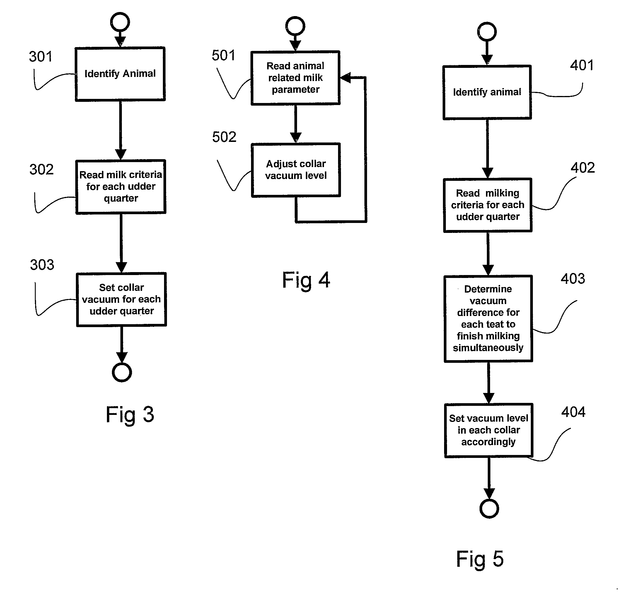
[0036]By increasing the vacuum difference for animals with high milk flow a more rapid milking can be achieved.

Problems solved by technology

During milking in automated milking machines one common problem is that not all udder quarters finish milking simultaneously.
This means that to draw all milk from the udder quarter finishing last, some udder quarters will be over-milked, resulting in bad treatment of these teats.

Method used


Image

  • Controlled collar vacuum
  • Controlled collar vacuum
  • Controlled collar vacuum

Examples


Embodiment Construction

[0048]In the following description, for purposes of explanation and not limitation, specific details are set forth, such as particular techniques and applications in order to provide a thorough understanding of the present invention. However, it will be apparent to one skilled in the art that the present invention may be practiced in other embodiments that depart from these specific details. In other instances, detailed descriptions of well-known methods and apparatuses are omitted so as not to obscure the description of the present invention with unnecessary details.

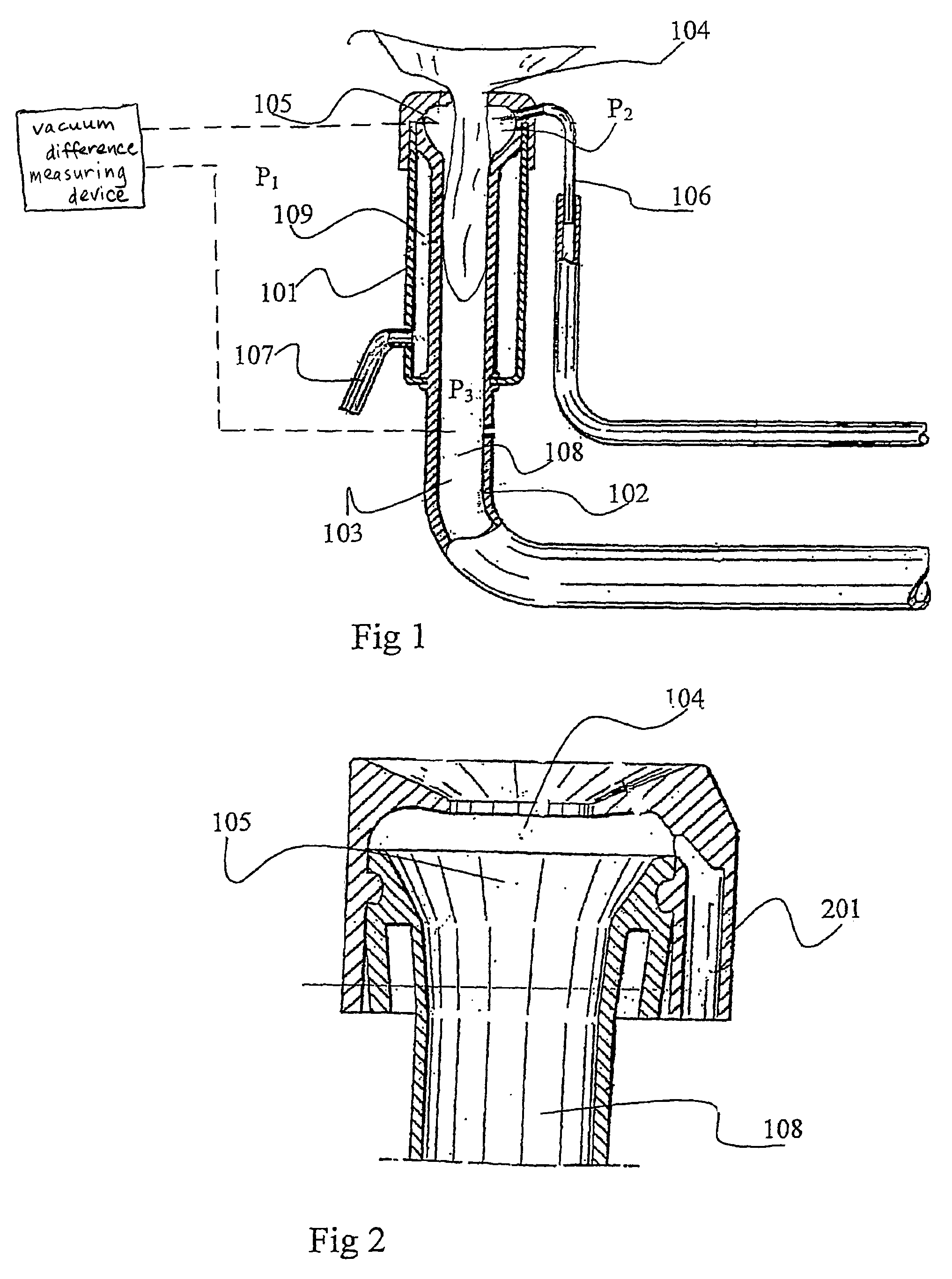
[0049]FIG. 1 is a schematic cross-sectional view of a per se known teat cup comprising a teat cup shell 101 and teat cup liner 102. The teat cup liner 102 comprises a lower end 103, a top end 104 and a space 105. A teat will be introduced into the teat cup liner 102 through the top end 104 and extend towards the lower end 103. A vacuum connection line 106 is connected to the space 105 and arranged to supply a vacuum lev...


PUM


Abstract

The present invention relates to a milking machine and a method for milking animal using a milking machine, wherein the milking machine comprises at least a first teat cup, the first teat cup is provided with a teat cup liner to be positioned around a teat of the milking animal, the teat cup liner comprises a lower end connected to a milking vacuum source for drawing milk from the milking animal, and a top end having a space and an orifice in which the teat is to be introduced, the teat cup liner further comprises an inlet to the space connected to a space vacuum source. The method is comprises the step of setting the vacuum level in the space so that the vacuum difference between the vacuum level in the lower end and the vacuum level in the space is related to a milking criteria for the particular udder quarter being milked.

Description

TECHNICAL FIELD[0001]The present invention relates to a milking machine for controlling the vacuum levels in a space of a teat cup liner and a method therefore.BACKGROUND OF THE INVENTION[0002]In machine milking systems it is important to milk the animal in an efficient manner, i.e. a fast and complete milking. That means that the milking of the animal should not take unnecessary long time and that all milk contained in the udder should be withdrawn and collected. This should also be performed while treating the animal and its teats gently so as not to inflict any pain or injuries.[0003]In this respect the design of teat cups, comprising teat cup shells and teat cup liners, as well as for instance applied vacuum levels, are important factors for achieving the above mentioned goals.[0004]Considerable efforts have been put in design of teat cups, especially teat cup liners of the teat cup to find solutions which treat the teats gently, and a number of different designs have been prese...

Claims


Application Information

Patent Timeline
Patent Type & Authority Patents(United States)
IPC IPC(8): A01J5/04A01JA01J5/007A01J5/08
CPCA01J5/08A01J5/007
Inventor ALVEBY, NILS
Owner DELAVAL HLDG AB
Why Eureka
Try Eureka