Deformable pads for rotary pad printing, apparatus and method
Inactive Publication Date: 2011-01-11
CLARK LLOYD DOUGLAS +1
View PDF7 Cites 8 Cited by
Summary
Abstract
Description
Claims
Application Information
AI Technical Summary
This helps you quickly interpret patents by identifying the three key elements:
Problems solved by technology
Method used
Benefits of technology
Problems solved by technology
Air entrapped during these operations would form pockets which would be undesirable since such pockets could release their contents in unpredictable ways, causing the ink image
Method used
Image
Click on the blue label to locate the original text in one second.
Reading with bidirectional positioning of images and text.
Examples
Example
First Embodiment
FIGS. 3A and 3B
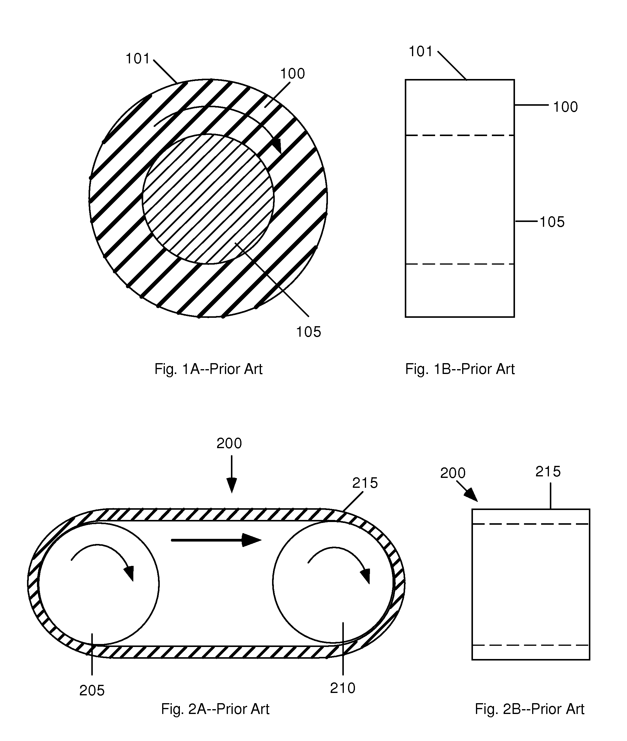
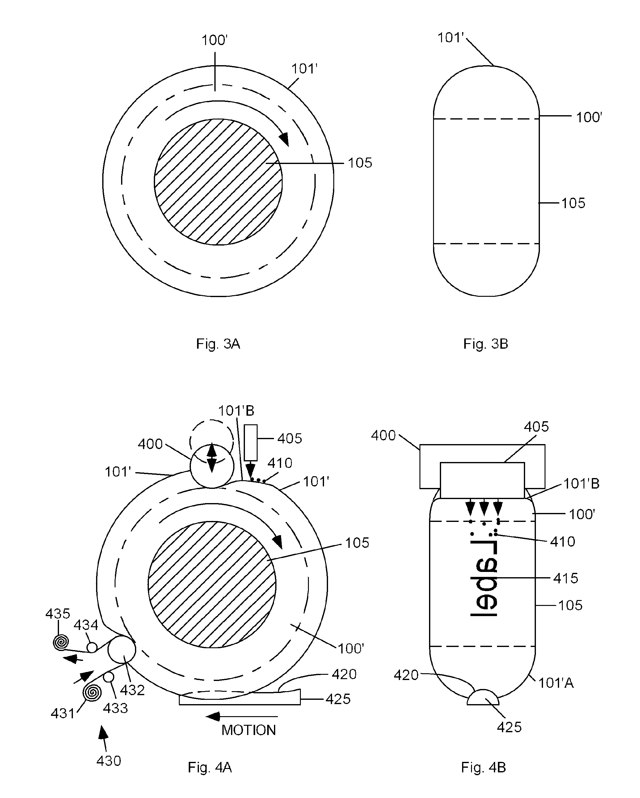
[0039]FIGS. 3A and 3B show side and front views, respectively, of a rotary pad according to a first aspect of a first embodiment. In this aspect, the volume of flexible material comprising pad 100′ (FIG. 3A) has a crowned surface 101′. Instead of having a right-circular cylindrical surface 101 (FIG. 1), surface 101′ of pad 100′ is bulged in its relaxed state. As in the prior-art pad, pad 100′ is bonded to a shaft 105. Shaft 105 is urged to rotate by a rotary drive mechanism (not shown). Pad 100′ and shaft 105 turn together in the direction indicated by the arrow. Pad 100′ is made of a resilient elastomer such as silicone rubber. The outer diameter of the pad is typically between one and 20 cm, although other sizes can be used. The width of the pad in the axial direction is typically between 0.5 and 10 cm, although other sizes can be used.
[0040]A pad according to this embodiment is useful in a system such as the one disclosed in our above co-pending pat...
PUM
Property
Measurement
Unit
Pressure
aaaaa
aaaaa
Length
aaaaa
aaaaa
Volume
aaaaa
aaaaa
Abstract
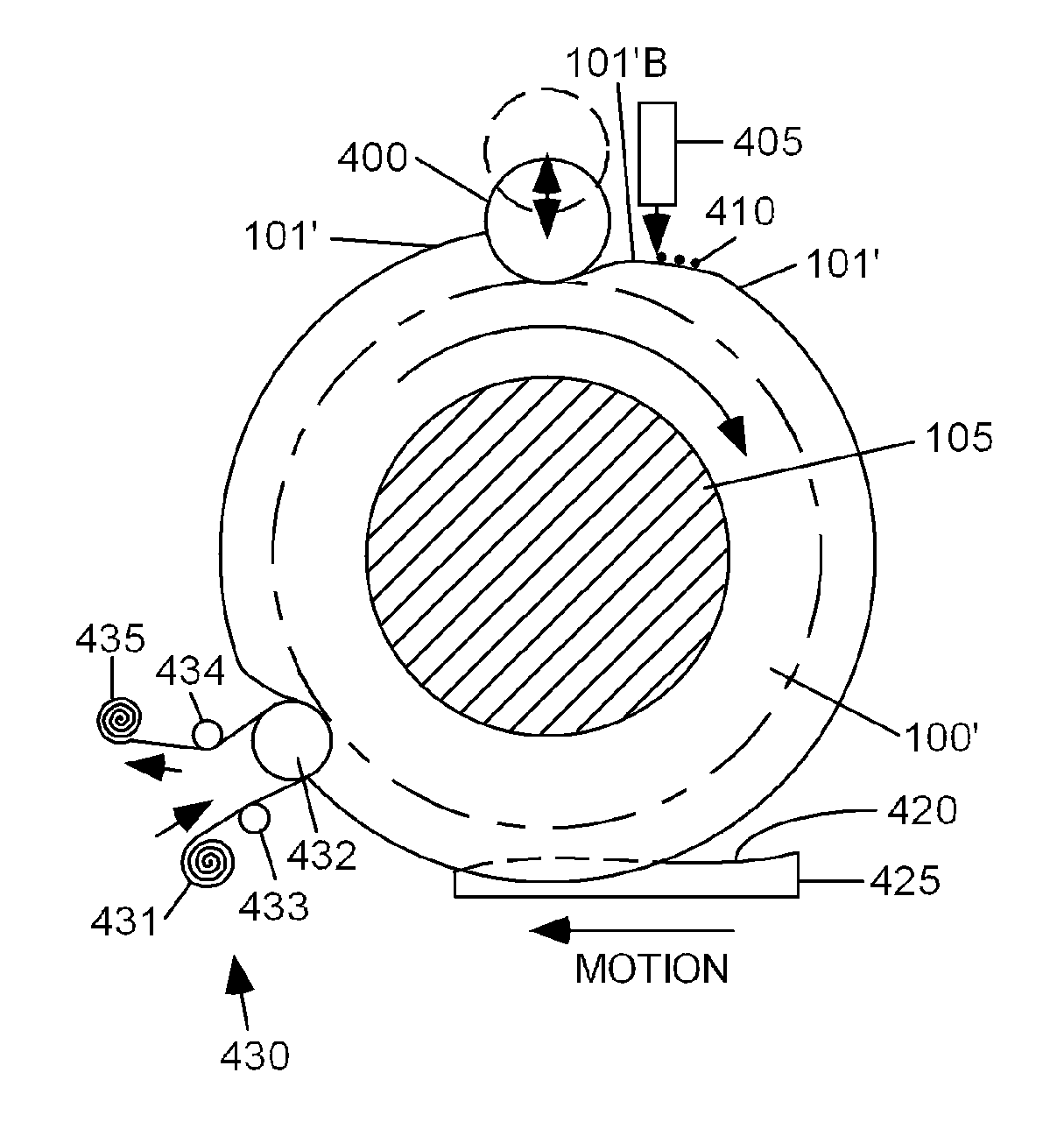
A rotary pad for pad printing comprises a cylinder (100′) or a belt (1105). The pad can be either flat or crowned in its relaxed condition. An ink applicator (405, etc.) applies an ink image (701) to the pad for subsequent transfer to a receiving object (425, etc.). If not initially flat, the pad can be flattened during application of the ink image, then forced to bulge for transfer to a receiving object. The pad can be flattened or caused to bulge by rollers (400, etc.) or by vacuum or pneumatic pressure. In one embodiment, an ink image is temporarily applied to the outer surface (510) of a flat cylindrical pad, then as the pad rotates, the sides of the pad are squeezed by rollers (520, 525), forcing the pad to bulge during transfer of the ink image to a receiving object (600). In another embodiment, a crowned pad (100′) is flattened while accepting an ink image, then allowed to resume its original crowned shape for transfer to a receiving object (425).
Description
CROSS-REFERENCE TO RELATED APPLICATIONS[0001]This application claims priority of our provisional patent application Ser. No. 60 / 825,304, filed Sep. 12, 2006. This application is related to and incorporates for reference purposes our U.S. Pat. No. 6,840,167 (2005) and our pending U.S. patent application Ser. No. 11 / 464,203, filed Aug. 13, 2006, Ser. No. 11 / 558,911, filed Nov. 11, 2006, Ser. No. 11 / 697,171, filed Apr. 5, 2007, and Ser. No. 11 / 777,166, filed Jul. 12, 2007.BACKGROUND[0002]1. Field[0003]The field is pad printing, and in particular rotary transfer pad printing.[0004]2. Prior Art[0005]Fixed Pad Printing[0006]Prior-art, fixed-pad printing is used to apply images and text to either flat or uneven surfaces ranging from poker chips and golf balls to household appliance panels. Such printing usually employs a domed pad. The pad is made of an elastomeric material such as gelatin or a silicone rubber. The surface of a flat, metal or plastic plate is etched to a depth of about 0.0...
Claims
Application Information
Patent Timeline
Application Date:The date an application was filed.
Publication Date:The date a patent or application was officially published.
First Publication Date:The earliest publication date of a patent with the same application number.
Issue Date:Publication date of the patent grant document.
PCT Entry Date:The Entry date of PCT National Phase.
Estimated Expiry Date:The statutory expiry date of a patent right according to the Patent Law, and it is the longest term of protection that the patent right can achieve without the termination of the patent right due to other reasons(Term extension factor has been taken into account ).
Invalid Date:Actual expiry date is based on effective date or publication date of legal transaction data of invalid patent.
