Thermal airflow tool and system

a technology of airflow and tool, applied in the field of medical devices and systems, can solve the problem of complicated thermal procedures and other problems

Inactive Publication Date: 2009-09-08
VALENS ASSOC INC
View PDF13 Cites 81 Cited by
  • Summary
  • Abstract
  • Description
  • Claims
  • Application Information

AI Technical Summary

Benefits of technology

[0016]In another embodiment of the invention, the thermal airflow tool is provided with a fixed resistor of about 1000 ohms enabling repeated use of the thermal airflow tool for burning an orifice with a pre-set diameter in eye capsulotomy surgery.

Problems solved by technology

In eye cataract surgery, for example, the thermal procedure is usually complicated by the need for multiple instruments: a cutting tool, an air pressure inlet, a water pressure inlet, and related surgical and electrical equipment.

Method used


Image

  • Thermal airflow tool and system
  • Thermal airflow tool and system
  • Thermal airflow tool and system

Examples


Embodiment Construction

[0029]The present invention provides a system for surgical thermal procedures, such as for capsulotomy in eye cataract surgery, and a dual-purpose thermal airflow tool generally useful in this as well as in other kinds of surgical procedures. The system comprises two main parts, an air pressure unit and a thermal power unit connected to a thermal airflow tool.

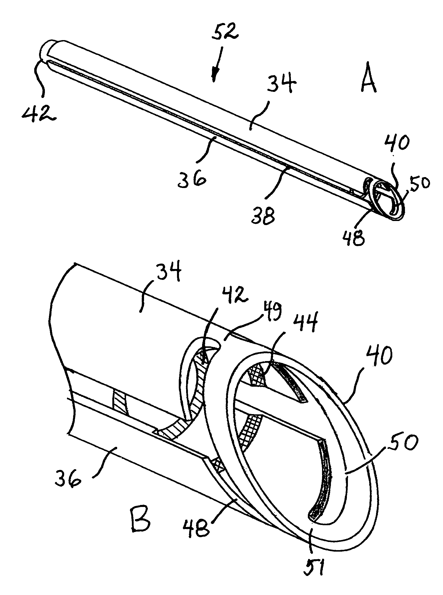
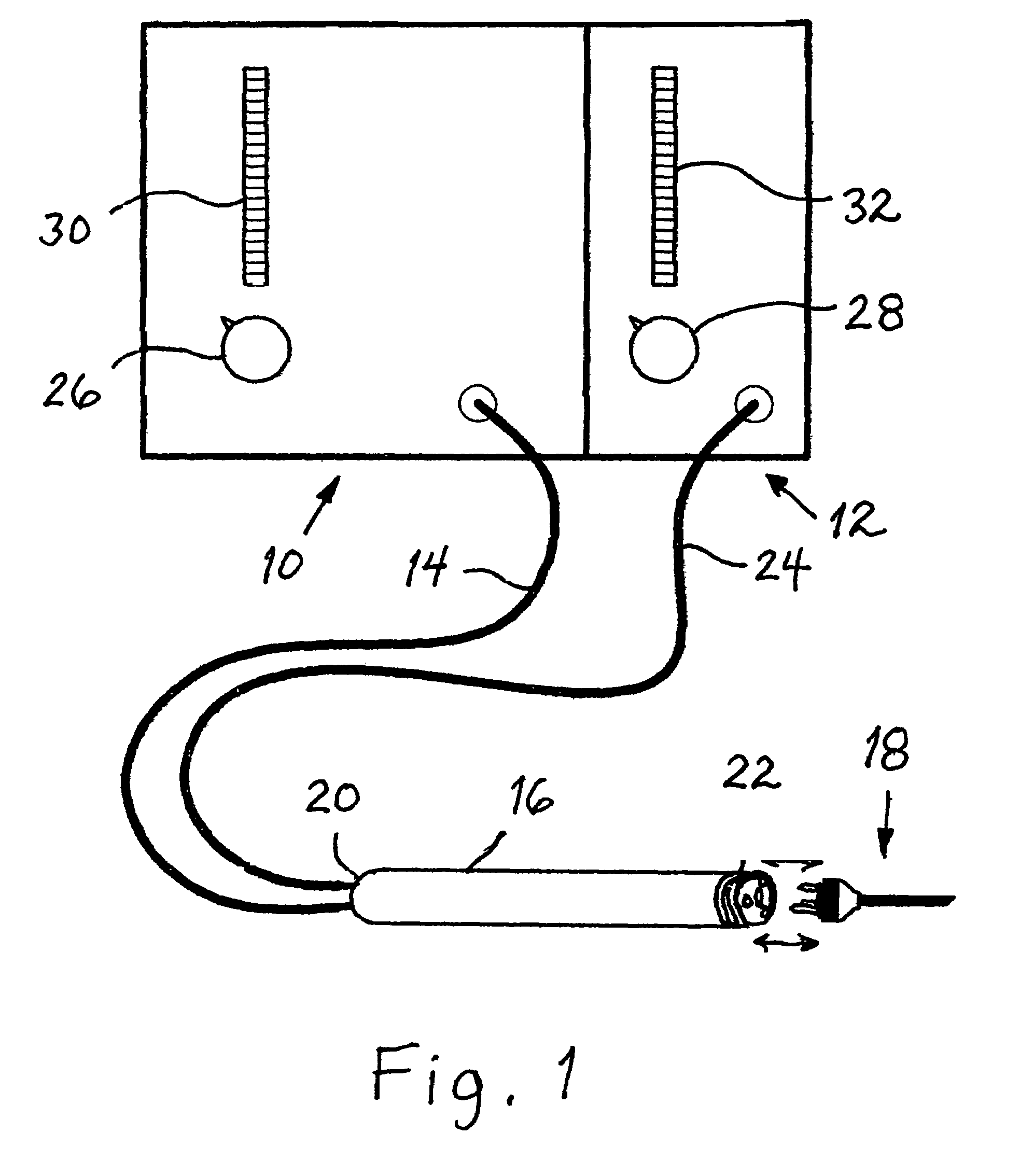
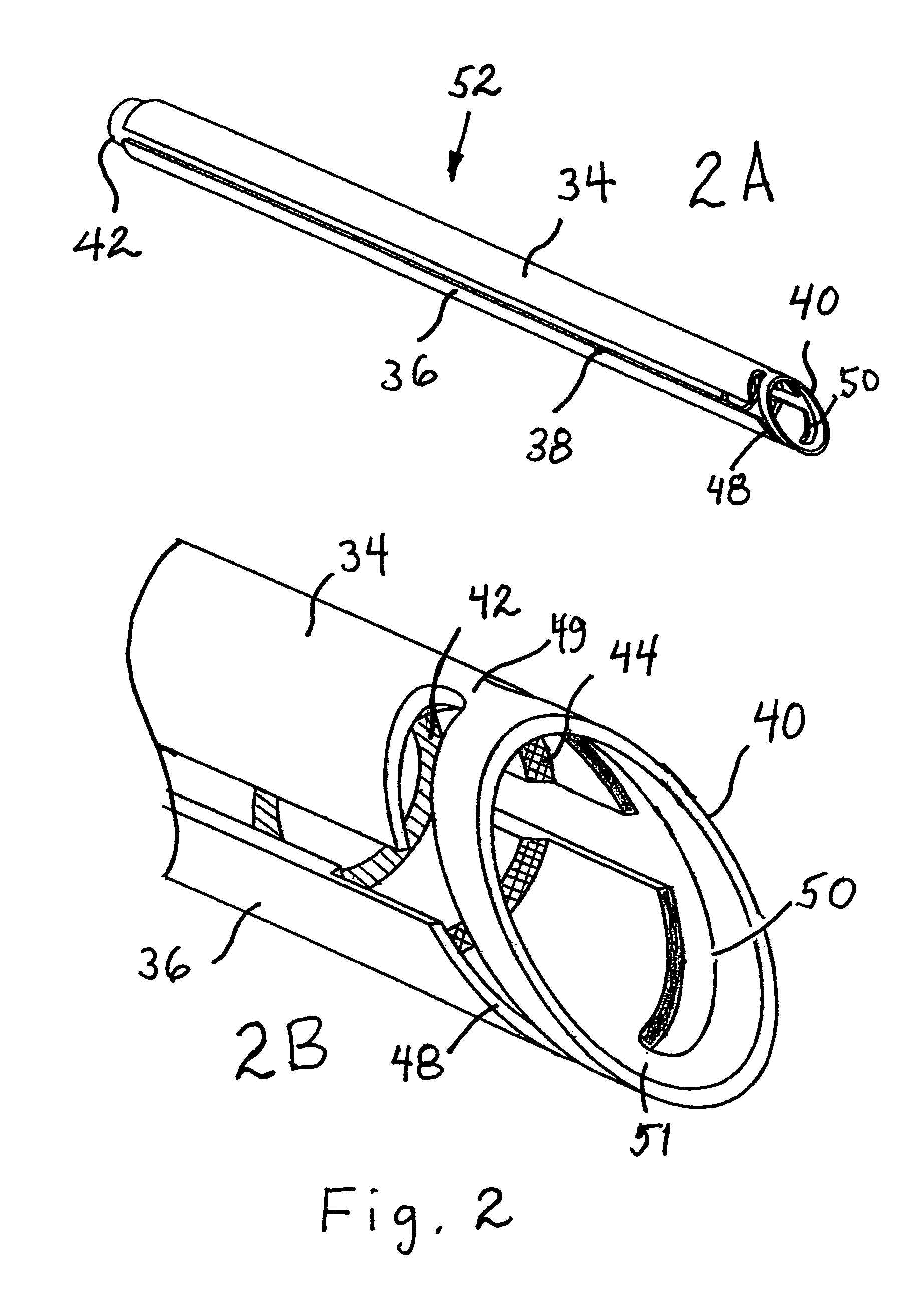
[0030]Referring now to FIG. 1, there is shown a general view of the layout of the major components comprising the system of the invention in accordance with an embodiment thereof. An air pressure unit 10 provides pressurized air for the system, while a thermal power unit 12 provides regulated heating, suitable, for example, for safely performing capsulotomy in eye cataract surgery (see FIG. 9). An air pressure input pipe 14 passes through a hollow handle 16 and directs airflow into thermal airflow tool 18 along a tube (see FIG. 2) passing through the central axis of both handle 16 and thermal airflow tool 18 when joined, as by ...


PUM


Abstract

A combination pressurized airflow and thermal cutting tool constructed as a dual-use thermal airflow tool for directed heating and drying of a specific area in surgical procedures, such as, by way of example, in eye cataract surgery where it is primarily used for needs related to the operation of a thermal cutting tool. The thermal airflow tool comprises a probe having an elongated, hollow body adapted to provide electrical power to a burning ring formed at a distal end thereof, and an air channel for conducting pressurized airflow to the distal end of the probe, with at least two apertures radially disposed at the distal end of the probe. The thermal airflow tool is in physical and electrical connection with an air pressure unit and thermal power unit, respectively, for directing and concentrating at least one of the pressurized airflow and heat at the distal end of the thermal airflow tool onto a surgical area when electrical power is applied to the thermal airflow tool.

Description

[0001]This application claims priority to US Provisional Application 60 / 531,629 filed on Dec. 23, 2003.FIELD OF THE INVENTION[0002]The present invention relates generally to medical devices and systems, and more particularly to a thermal airflow tool and an associated system for improving theremal surgical procedure.BACKGROUND OF THE INVENTION[0003]Thermal surgical procedure is improved and made more efficient by concentrating heat at a position proximate to a surgical site. In eye cataract surgery, for example, the thermal procedure is usually complicated by the need for multiple instruments: a cutting tool, an air pressure inlet, a water pressure inlet, and related surgical and electrical equipment. It would be useful to simplify such surgical procedures by providing a combination tool that concentrates heat on the surgical site and which is constructed so as to be convenient to handle and which can be used for providing both regulated heating and airflow pressure directed to a su...

Claims


Application Information

Patent Timeline
Patent Type & Authority Patents(United States)
IPC IPC(8): A61B18/18A61B18/04A61B18/08A61F9/007
CPCA61B18/082A61F9/007A61B2018/048
Inventor BEN-NUN, JOSHUA
Owner VALENS ASSOC INC
Why Eureka
Try Eureka