Automatic portable pneumatic compression system

a portable, automatic technology, applied in the field of compressive pressure systems, can solve the problems of imposing total confinement on the patient during treatment, heavy unit, difficult maneuverability and placement in the vicinity of patients, etc., to achieve the effect of expanding the life expectancy of patients, reducing the power consumption of the pump unit, and compactness

Inactive Publication Date: 2006-06-20
ZIMMER SURGICAL
View PDF56 Cites 83 Cited by
  • Summary
  • Abstract
  • Description
  • Claims
  • Application Information

AI Technical Summary

Benefits of technology

[0010]In one aspect of the invention, the pump unit can be operated alternatively as a foot pump, calf pump or a simultaneous foot and calf pump. In another aspect, a combination of self operated relief valves and check valves can be used for the inflation and deflation of the sleeve cells, thus achieving additional compactness and lower power consumption of the pump unit, and uses only one air conduit between the pump unit and the sleeve. In yet another aspect, while the system is connected to a conventional electrical power outlet, the rechargeable batteries can be bypassed and recharged only if necessary, thus expanding their life expectancy. Yet in another aspect, the pump unit can use an accumulator in order to speed the time needed for the inflation of each cell.
[0011]Accordingly, the invention provides a system for applying compressive pressure to a limb in which the pump unit is small, light weight, ambulant and can operate independent of electrical power supply outlets, and utilizes a small fl

Problems solved by technology

First, they use the conventional main power supply (wall outlet), and thus impose total confinement on the patient during treatment.
The pump unit is heavy (5–15 pounds), which makes it hard to maneuver and place in the vicinity of the patients.
The pump unit is big and thus creates a storage problem, specifically in hospitals, in which a few units are stationed, usually in a special storage room.
The sleeve is big and ungainly, and thus restricts the movement of the limb it encompasses and imposes an aesthetic discomfort.
In addition, the use of multiple cells demands the use of multiple conduits (usually one for each cell) making the whole system more cumbersome and harder to maneuver.
All of the aforementioned disadvantages result in poor patient and therapist (mainly nurses) compliant, resulting in that the devices are used for treatment only to the most severe cases of the medical indications described above.
As a consequence, the devices need a large compressor that require high current supply, which forces their connection to the electrical outlets for power supply.
Home use

Method used


Image

  • Automatic portable pneumatic compression system
  • Automatic portable pneumatic compression system
  • Automatic portable pneumatic compression system

Examples


Embodiment Construction

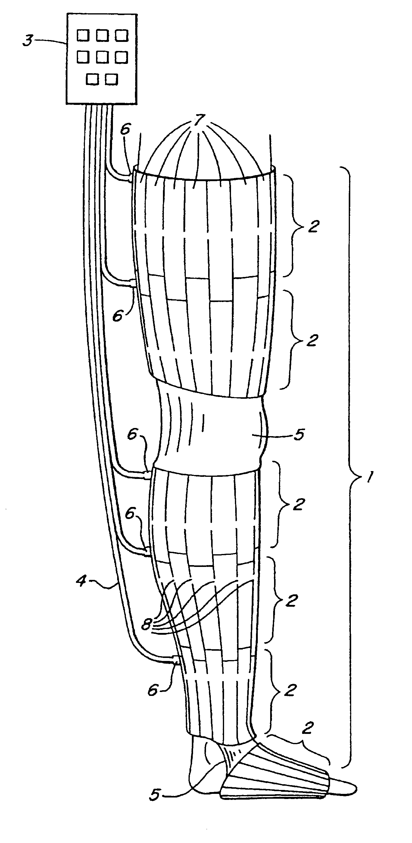
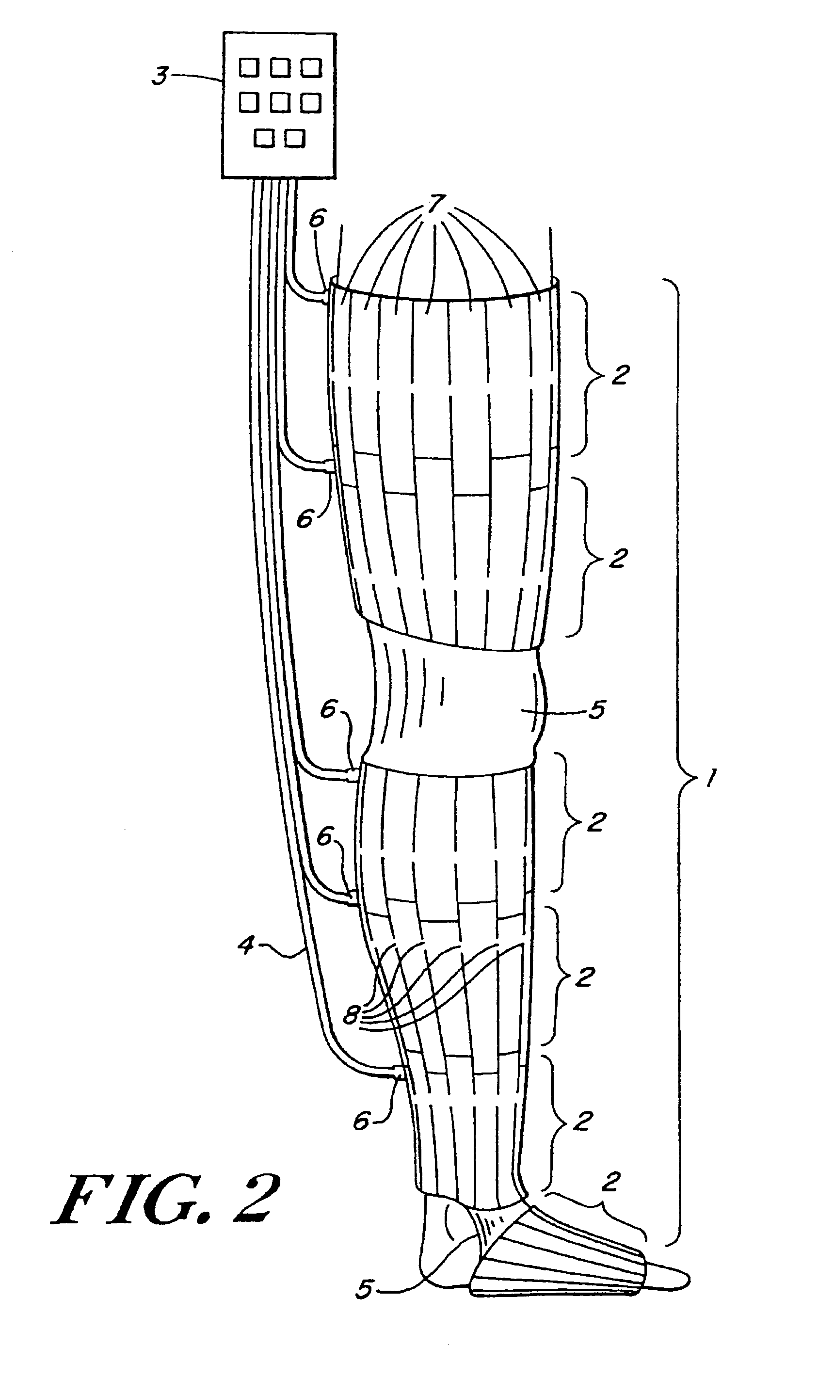
[0024]In the following, ,in embodiment of the invention will be described for use on the leg of an individual. However, it is to be understood that the invention is also intended for use on any body limb such as an arm, a foot, a part of a leg, arm or foot, and may be used on two or more limbs simultaneously.

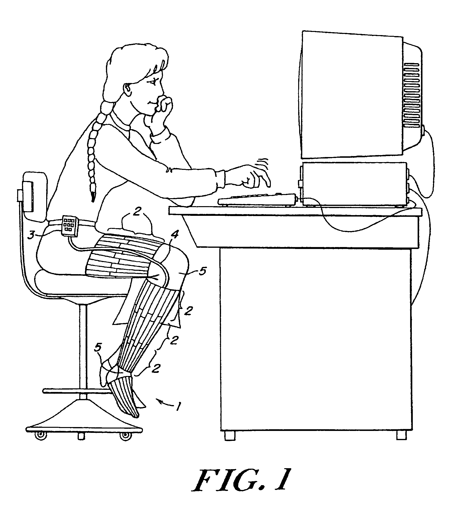
[0025]In FIG. 1, a patient is depicted wearing a massaging sleeve 1 of the invention on her leg while carrying out her routine duties. In FIG. 1, the trouser leg of the patient is cut away to reveal the sleeve. In practice, however, the sleeve remains concealed from view, and remains unnoticed even during operation when the cells are intermittently inflated. The sleeve 1 has an inner and outer surface composed of a durable flexible material and is divided into a plurality of cells 2 along its length and each cell is connected to the control unit 3 by a separate tube collectively labeled 4 in FIG. 1. Sections of the sleeve may be of non-inflatable elastic material 5, for example ...


PUM


Abstract

An automatic portable ambulant miniaturized system for applying pneumatic pressure to a body limb including a portable ambulant hand-held fluid source unit, a conduit for delivering fluid generated by the unit, and a sleeve coupled to the conduit and adapted to envelop a body limb. The sleeve contains one or more individually inflatable cells, each cell being subdivided into two or more longitudinally extending confluent compartments along the axis of the body limb. The compartments are inflated and deflated essentially simultaneously by the portable fluid source unit.

Description

[0001]This application is a continuation application of U.S. patent application Ser. No. 09 / 413,968, filed Oct. 7, 1999 (now U.S. Pat. No. 6,494,852), which is a continuation-in-part of U.S. patent application Ser. No. 09 / 038,157, filed Mar. 11, 1998 (now U.S. Pat. No. 6,478,757), and is related to U.S. patent application Ser. No. 09 / 375,083 filed Aug. 16, 1999 (now U.S. Pat. No. 6,447,467).BACKGROUND OF THE INVENTION[0002]The invention relates to systems for applying compressive pressures against a patient's limb, specifically to a miniaturized, automatic portable ambulant system.[0003]Various conventional compression devices are known for applying compressive pressure to a patient's limb. These types of devices are used to assist in a large number of medical indications, mainly the prevention of deep vein thrombosis (DVT), vascular disorders, reduction of edemas and the healing of wounds. Prior art devices are typically divided into two main segments: 1) a hospital segment, in whi...

Claims


Application Information

Patent Timeline
IPC IPC(8): A61H9/00A61H23/04A61F5/01
CPCA61F5/012A61H9/0078A61H2205/10A61H2201/5007
Inventor BARAK, JAKOBNAVEH, YOAVEHRLICH, SHARON
Owner ZIMMER SURGICAL
Why Eureka
Try Eureka