Pneumatically actuated magnetic workpiece holder

a magnetic workpiece and pneumatic actuator technology, applied in the direction of magnetic bodies, manufacturing tools, borehole/well accessories, etc., can solve the problems of affecting the workpiece holding effect, the device is often larger and heavier than may be desirable, and the gripping device cannot be used to lift a wide variety of differently shaped workpieces. to achieve the effect of preventing damage to the workpiece being held

Inactive Publication Date: 2003-03-25
INDAL MAGNETICS
View PDF7 Cites 80 Cited by
  • Summary
  • Abstract
  • Description
  • Claims
  • Application Information

AI Technical Summary

Benefits of technology

According to one feature of this invention, a polymeric boot or cover is provided for the contact surface to thereby prevent damage to the workpiece being held. The polymeric cover preferably comprises an ultra high molecular weight polymer, most preferably urethane.

Problems solved by technology

While these work in a generally satisfactory manner, such gripping devices are often cost-prohibitive since the gripping device is usually dedicated to one or a relatively few particularly-shaped workpieces.
Thus, such gripping devices cannot be used to lift a wide variety of differently shaped workpieces.
However, such devices are often larger and heavier than may be desirable.
Moreover, they consume large amounts of energy in order to continually magnetize the electromagnet.
Consequently, such devices can be quite expensive to build and operate.
Unfortunately, vacuum holding devices also suffer drawbacks.
Further costs associated with vacuum holding devices arise from the necessity of maintaining a constant vacuum in order to hold a workpiece.
This necessity for maintaining constant vacuum pressure also presents safety considerations, since a failure of the vacuum supply while a workpiece is being lifted poses obvious workplace hazards.
Vacuum holding devices are also less desirable for applications where workpieces with curved or irregularly-shaped surfaces must be lifted and held, since vacuum cups require a relatively flat contact surface in order to create an efficient seal.

Method used


Image

  • Pneumatically actuated magnetic workpiece holder
  • Pneumatically actuated magnetic workpiece holder
  • Pneumatically actuated magnetic workpiece holder

Examples


Embodiment Construction

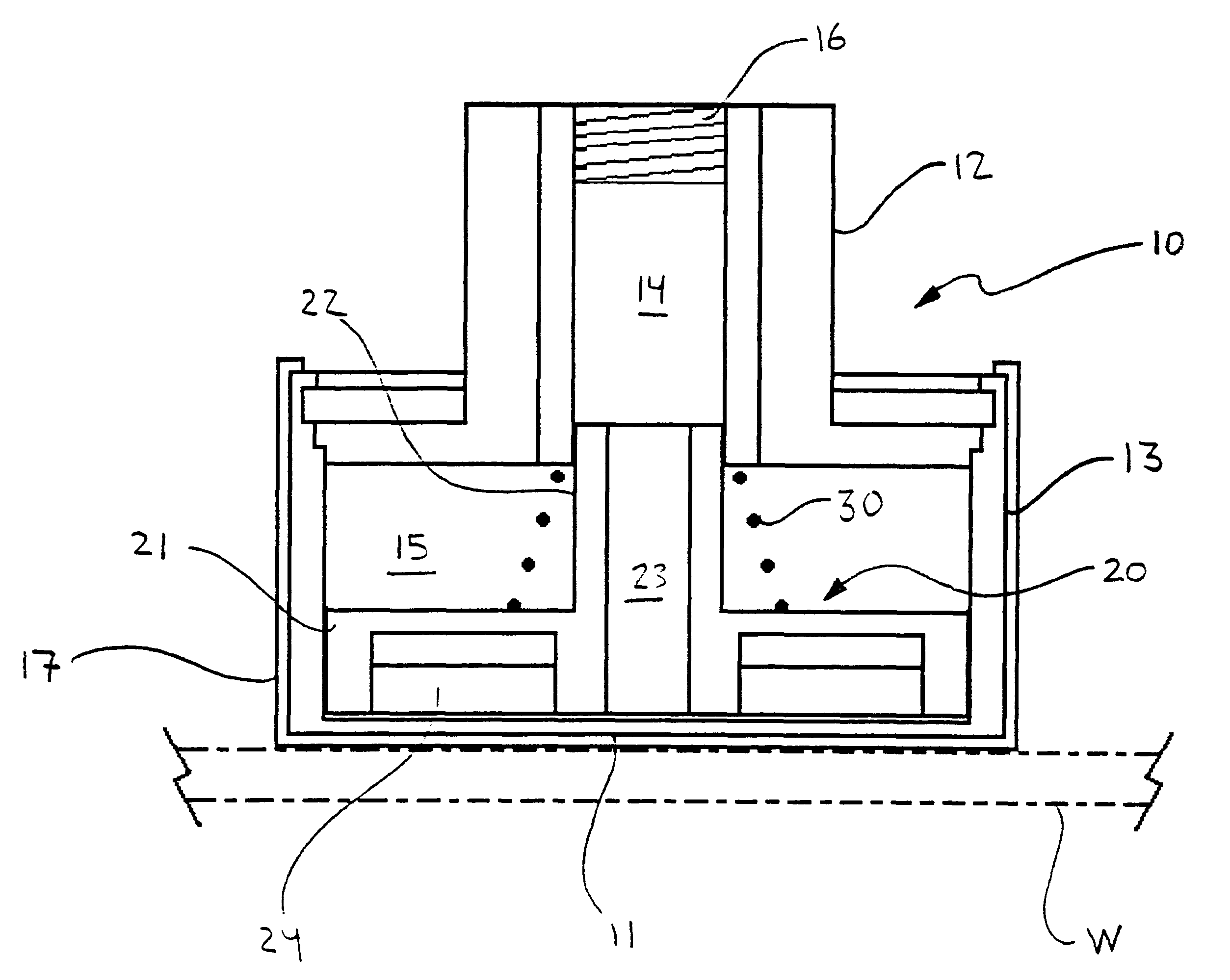
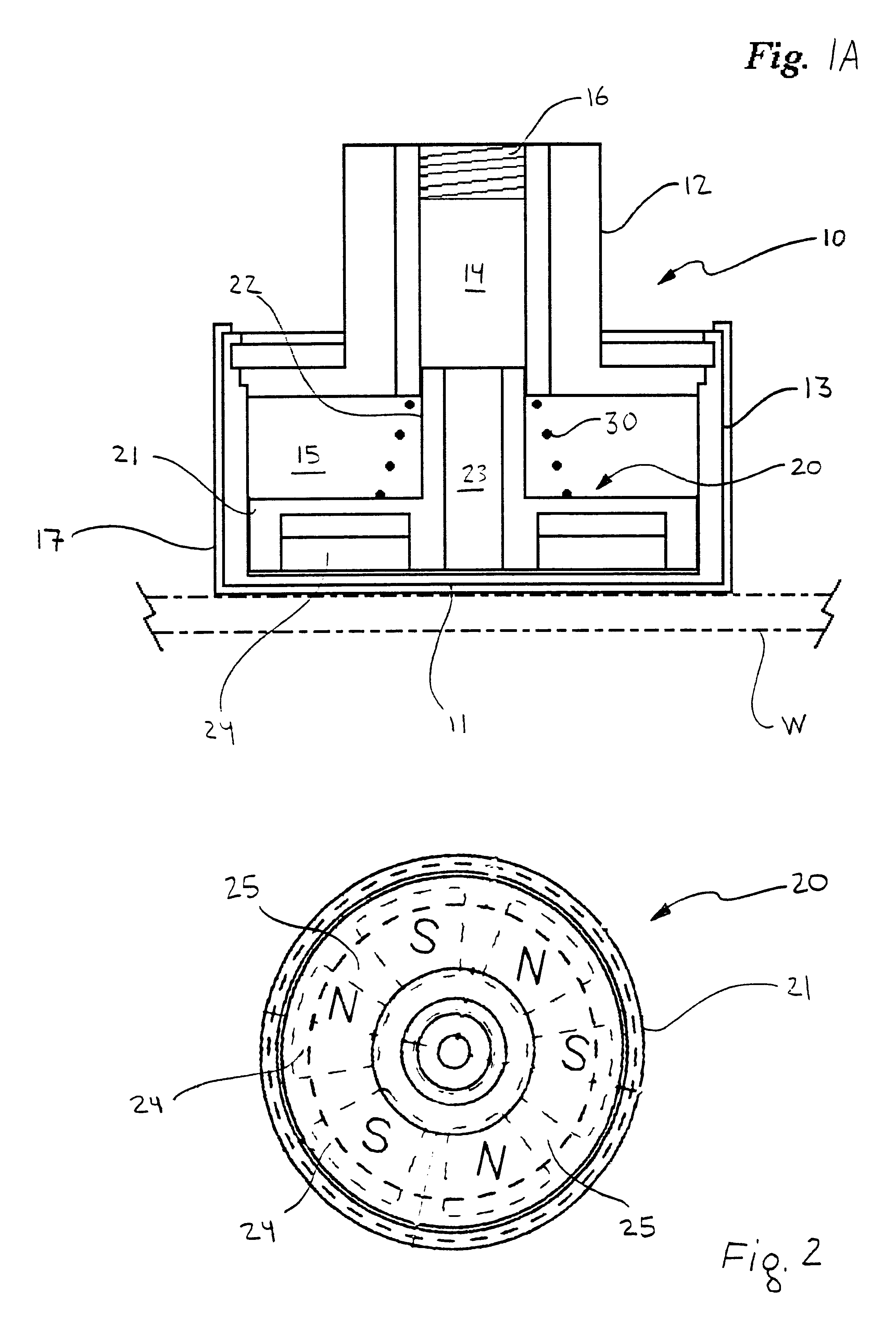
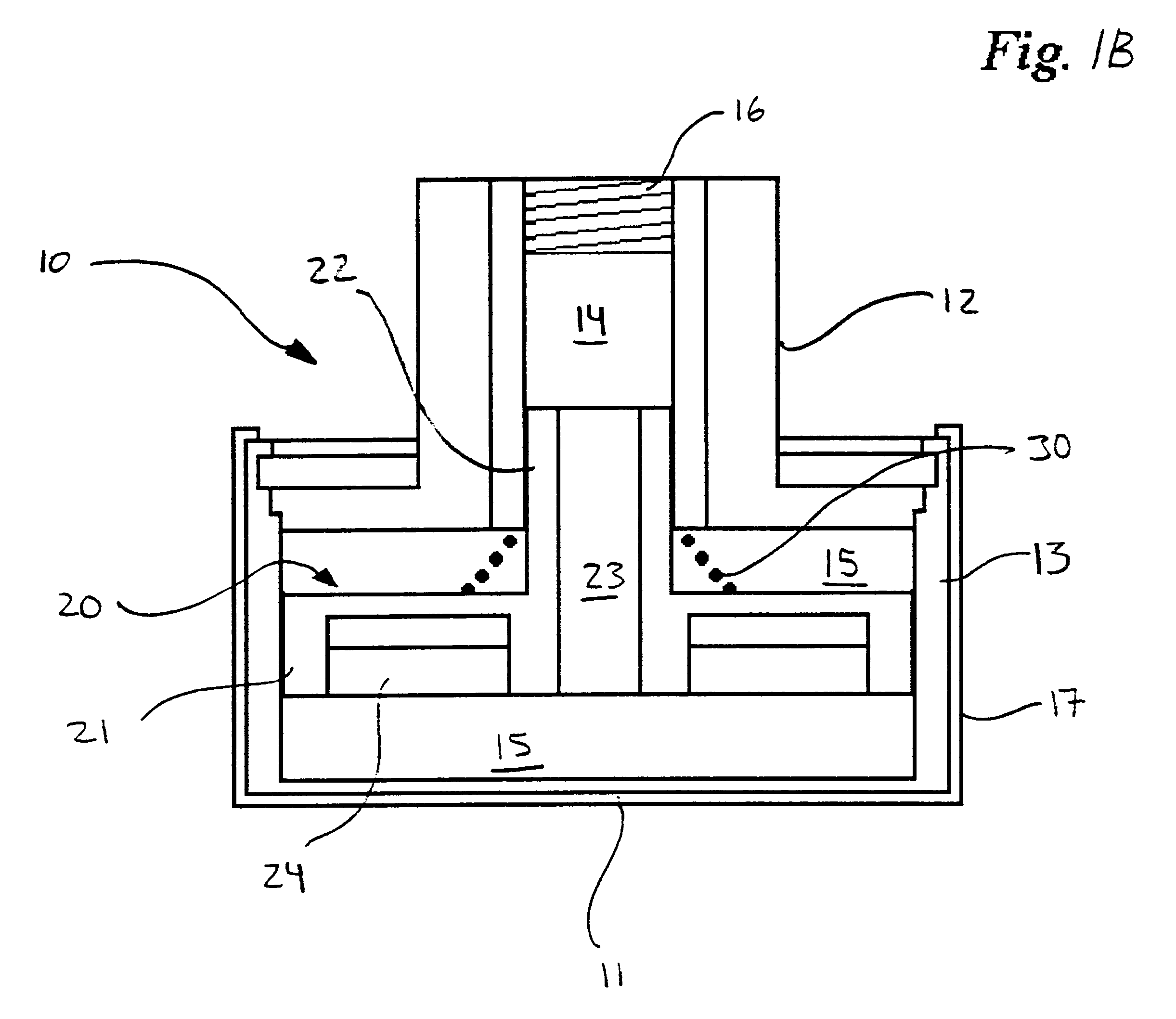
Referring now to the drawings, wherein like numerals indicate like or corresponding parts, the present invention will be seen generally to comprise a pneumatically actuated magnetic workpiece holder having essentially a housing or body portion 10 with a first end including a contact surface 11 for contacting a workpiece W (indicated in phantom) to be held, and a magnet assembly 20 translationally disposed in the housing. FIG. 1A. The magnet assembly 20 is biased, for instance by the illustrated compression spring 30, toward an operative position, shown in FIG. 1A, wherein the magnet assembly 20 is sufficiently near the contact surface 11 so as to exert on the workpiece W an attractive force sufficient for holding the workpiece in contact with the workpiece holder. The magnet assembly 20 is further translationally positionable by pneumatic pressure, as explained herein, towards an inoperative position, shown in FIG. 1B, wherein the magnet assembly 20 is sufficiently distant from the ...


PUM

PropertyMeasurementUnit
polaritiesaaaaaaaaaa
pneumatic pressureaaaaaaaaaa
attractive forceaaaaaaaaaa

Abstract

A pneumatically actuated magnetic workpiece holder comprising a housing having a contact surface for contacting a workpiece to be held, and a magnet assembly translationally disposed in the housing, the magnet assembly comprising a plurality of permanent magnets arranged so that adjacent magnets are of opposite polarities. The housing is adapted for fluid communication with a pneumatic supply. The magnet assembly is biased towards an operative position, according to which the magnet assembly is sufficiently near the contact surface to exert on a workpiece an attractive force sufficient for holding the workpiece in contact with the workpiece holder, and is translationally positionable by pneumatic pressure towards an inoperative position, according to which the magnet assembly is sufficiently distant from the contact surface so as to be unable to exert on the workpiece an attractive force sufficient for holding the workpiece in contact with the workpiece holder. The invention is adapted for replacing suction-cup workpiece holders in conventional vacuum lifting devices, and a method of utilizing the present invention in this fashion is taught to comprise providing the workpiece holder with a coupling complimentary to the coupling for such conventional suction-cup workpiece holders, so that the magnetic workpiece holder may be substituted for the conventional suction-cup holder in the vacuum lifting device. According to this method, the vacuum supply of the conventional vacuum lifting device is adapted to provide such positive air pressure for employing the magnetic workpiece holder of this invention.

Description

The present invention relates generally to workpiece holders, and more particularly to pneumatically actuated magnetic workpiece holders and a method for their use with conventional vacuum-type lifting devices.Many manufacturers, including automobile manufacturers, incorporate into their factories lifting assemblies which are manually, mechanically, or robotically operated. These lifting assemblies are utilized to move very heavy workpieces, often made from sheet metal or the like, from one operational area of an assembly line to another. Manufacturers are continually endeavoring to make these lifting assemblies as safe, powerful, efficient, and inexpensive to operate as possible.Lifting assemblies incorporate thereon or are provided with some type of device for holding an article or workpiece. Some of these devices include "hand"-like gripping devices. While these work in a generally satisfactory manner, such gripping devices are often cost-prohibitive since the gripping device is ...

Claims


Application Information

Patent Timeline
Patent Type & Authority Patents(United States)
IPC IPC(8): B25B11/00B66C1/04B66C1/00
CPCB66C1/04B25B11/002
Inventor HARDY, PAUL
Owner INDAL MAGNETICS
Why Eureka
Try Eureka