Fuel injection valve

a fuel injection valve and valve body technology, applied in the direction of fuel injection apparatus, fuel feed system, engine components, etc., can solve the problems of inability to reduce the minimum controllable injection quantity disadvantageously, difficult to control the quantity, and the needle of the fuel injection valve is less responsiv

Active Publication Date: 2011-01-11
DENSO CORP
View PDF16 Cites 10 Cited by
  • Summary
  • Abstract
  • Description
  • Claims
  • Application Information

AI Technical Summary

Benefits of technology

[0009]In order to solve this problem, a fuel injection valve is proposed, in which the movable core and the stator have a large contact area between them. As a result, the large contact area enlarges squeezing force developed between the movable core and the stator, and thereby a small bounce occurs when the coil of the fuel injection valve is supplied with current in the event of opening the valve. However, the large squeezing force makes the needle of the fuel injection valve less responsive in the event of closing the valve. This disadvantageously increases the minimum controllable injection quantity or causes another disadvantage associated with the injection characteristic of the fuel injection valve.
[0009]In order to solve this problem, a fuel injection valve is proposed, in which the movable core and the stator have a large contact area between them. As a result, the large contact area enlarges squeezing force developed between the movable core and the stator, and thereby a small bounce occurs when the coil of the fuel injection valve is supplied with current in the event of opening the valve. However, the large squeezing force makes the needle of the fuel injection valve less responsive in the event of closing the valve. This disadvantageously increases the minimum controllable injection quantity or causes another disadvantage associated with the injection characteristic of the fuel injection valve.
[0009]In order to solve this problem, a fuel injection valve is proposed, in which the movable core and the stator have a large contact area between them. As a result, the large contact area enlarges squeezing force developed between the movable core and the stator, and thereby a small bounce occurs when the coil of the fuel injection valve is supplied with current in the event of opening the valve. However, the large squeezing force makes the needle of the fuel injection valve less responsive in the event of closing the valve. This disadvantageously increases the minimum controllable injection quantity or causes another disadvantage associated with the injection characteristic of the fuel injection valve.
[0009]In order to solve this problem, a fuel injection valve is proposed, in which the movable core and the stator have a large contact area between them. As a result, the large contact area enlarges squeezing force developed between the movable core and the stator, and thereby a small bounce occurs when the coil of the fuel injection valve is supplied with current in the event of opening the valve. However, the large squeezing force makes the needle of the fuel injection valve less responsive in the event of closing the valve. This disadvantageously increases the minimum controllable injection quantity or causes another disadvantage associated with the injection characteristic of the fuel injection valve.
[0125]In a case, where the area ratio is lower than 3%, it may be impossible to sufficiently reduce the fluid resistance applied to the movable core 22 in the event of opening and closing the fuel injection valve 1. As a result, the responsibility of the valve member 40 may deteriorate. In another case, where the area ratio is higher than 12%, it may also be impossible to sufficiently secure the magnetic attractive force that is required to open the fuel injection valve 1.

Problems solved by technology

As a result, particularly if the fuel injection valve 91 is driven for a short period of time, the injection quantity is not proportional to the time period, so that the quantity is difficult to control.
As a result, it is impossible to reduce the minimum controllable injection quantity disadvantageously.
However, the large squeezing force makes the needle of the fuel injection valve less responsive in the event of closing the valve.
This disadvantageously increases the minimum controllable injection quantity or causes another disadvantage associated with the injection characteristic of the fuel injection valve.

Method used


Image

  • Fuel injection valve
  • Fuel injection valve
  • Fuel injection valve

Examples


first embodiment

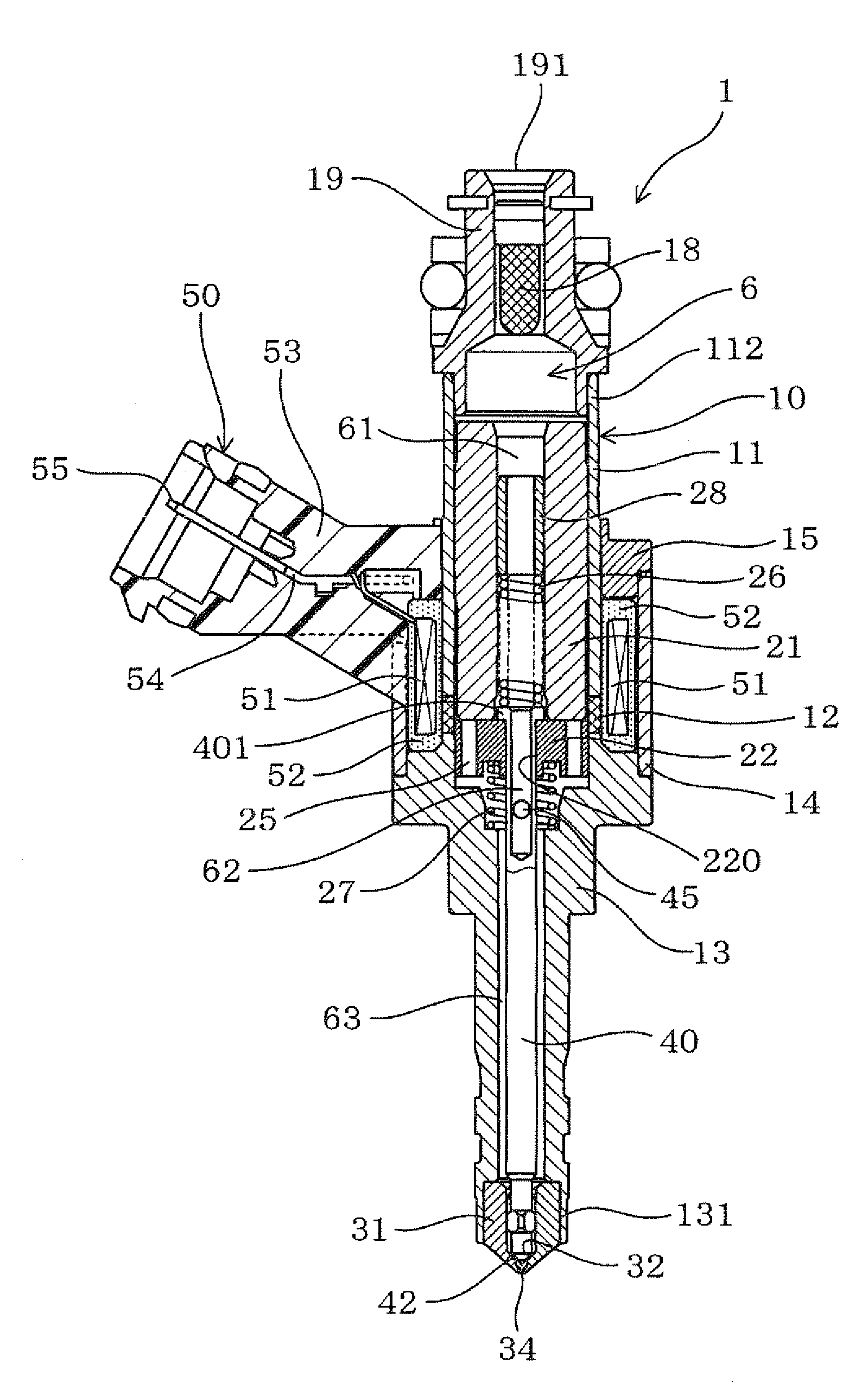
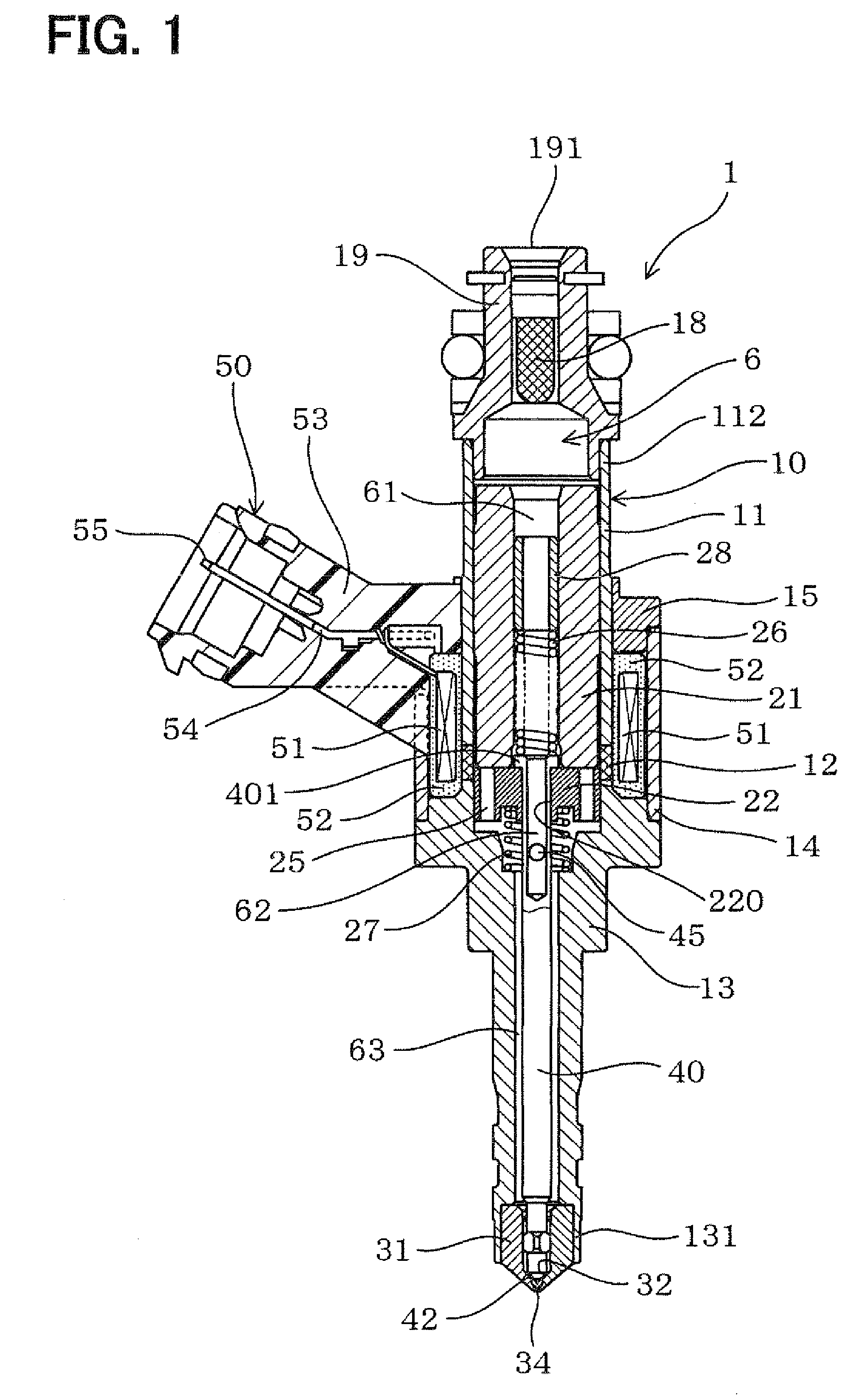
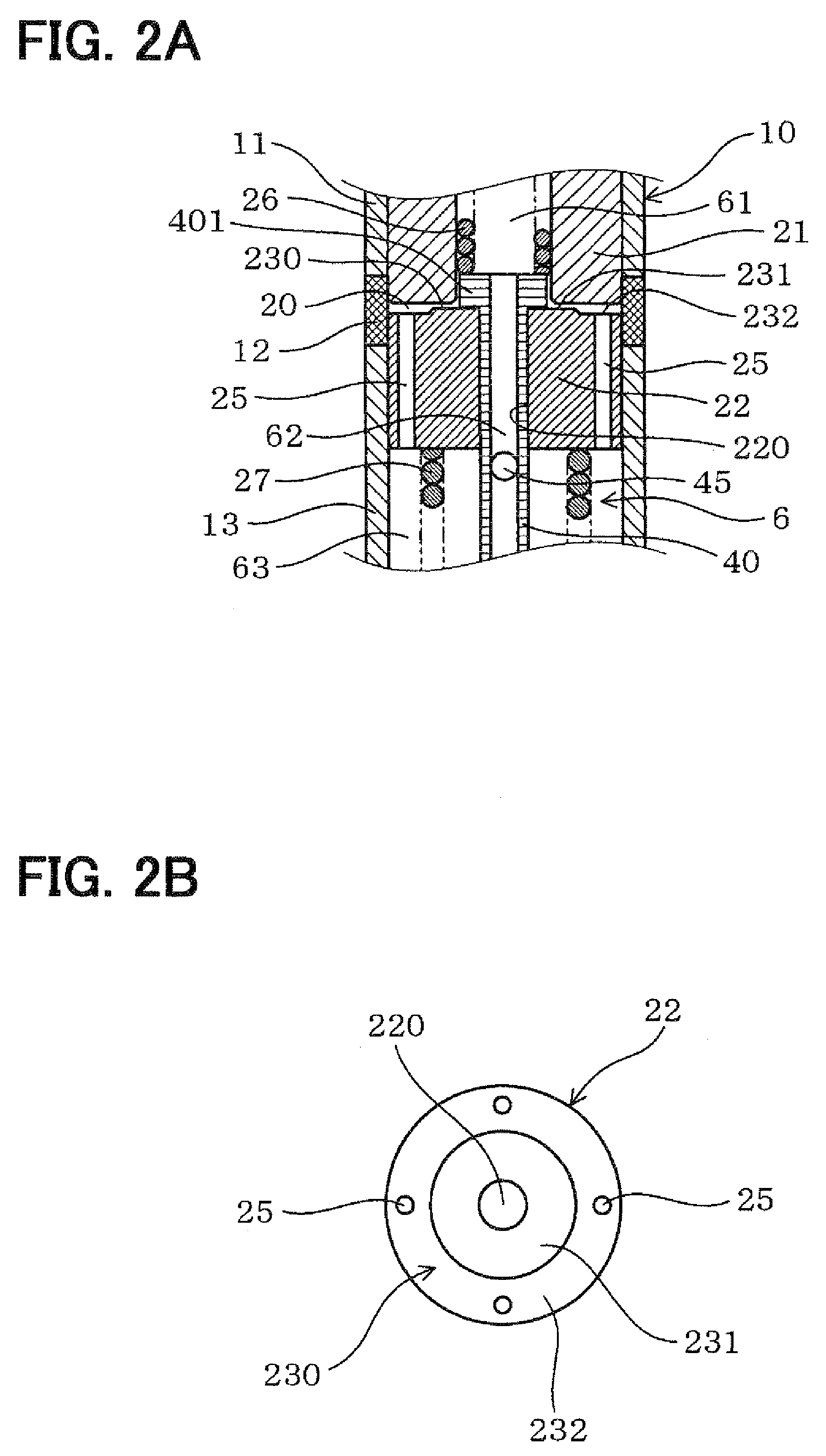
[0041]FIGS. 1, 2A, 2B, and 3 show a fuel injection valve (an injector) 1 according to the first embodiment of the present invention.

[0042]With reference to FIG. 1, the fuel injection valve 1 is mounted on the head of a direct-injection gasoline engine (not shown) but may be alternatively used for an indirect-injection gasoline engine or a diesel engine.

[0043]The fuel injection valve 1 has a nozzle hole 34 formed at a front end of the valve 1. The front end of the fuel injection valve 1 corresponds to a downstream side of the fuel injection valve 1 in a flow direction of fuel. Also, a rear end of the fuel injection valve 1 corresponds to an end of the valve 1 opposite from the front side, and corresponds to an upstream side of the valve 1 in the flow direction.

[0044]The fuel injection valve 1 includes a tubular housing 10 that defines a fuel channel 6 therein. The housing 10 includes a pipe 11, a tubular non-magnetic part 12, and a tubular holder 13, which are integrated with each ot...

second embodiment

[0088]FIGS. 5A to 7B show fuel injection valves according to the second embodiment of the present invention. In each of these valves, the movable core 22 has communicating passages 25 positioned differently from those in the first embodiment.

[0089]In each of FIGS. 5A, 6A, and 7A, the movable core 22 is in contact with the stator 21.

[0090]FIGS. 5A and 5B show a fuel injection valve in which the movable core 22 has four communicating passages 25 formed to extend through the movable core 22 as is the case with the first embodiment.

[0091]In FIGS. 5A and 5B, the communicating passages 25 are rectangular in section and positioned at intervals of 90 degrees near the outer periphery of the movable core 22.

[0092]In this case, the second communicating passage 25 sufficiently has the effect of improving the responsibility of the valve member 40, and thereby improving the injection characteristic of the fuel injection valve 1. In addition, the second communicating passage 25 is easy to form by ...

third embodiment

[0099]FIGS. 8A to 11B show fuel injection valves according to the third embodiment of the present invention. In each of these valves, the stator 21 defines communicating passages 24 therein in place of the communicating passages 25 of the movable core 22 in the first and second embodiments.

[0100]As shown in FIGS. 8A to 11B, the stator 21 defines the communicating passages 24 that connect the annular space 20 with the fuel passage 61, which corresponds to the first fuel passage of the fuel channel 6 positioned upstream of the movable core 22.

[0101]In each of FIGS. 8A, 9A, 10A, and 11A, the movable core 22 is in contact with the stator 21.

[0102]FIGS. 8A to 9B show fuel injection valves in each of which the stator 21 defines four communicating passages 24 therein that extend through the stator 21.

[0103]More specifically, in FIGS. 8A and 8B, the communicating passages 24 extend open at the inner peripheral surface 211 of the stator 21 and to open at the front end face 210 of the stator,...


PUM


Abstract

A fuel injection valve includes a housing, a stator, a movable core, a coil, a nozzle hole, a valve member, and at least one communicating passage. The housing receives the stator and movable core. An end face of the movable core has a non-contact surface and a contact surface. The non-contact surface and the stator define a space when the contact surface contacts the stator. The valve member is slidably received in a bore of the movable core. The valve member has a stopper engageable with the movable core such that the valve member is axially movable together with the movable core. The at least one communicating passage connects the space with a corresponding one of a first fuel passage and a second fuel passage of the housing.

Description

CROSS REFERENCE TO RELATED APPLICATION[0001]This application is based on and incorporates herein by reference Japanese Patent Application No. 2007-330282 filed on Dec. 21, 2007.BACKGROUND OF THE INVENTION[0002]1. Field of the Invention[0003]The present invention relates to a fuel injection valve for injecting fuel into an internal combustion engine or the like.[0004]2. Description of Related Art[0005]A conventional fuel injection valve includes a needle (valve member), which is driven electromagnetically to inject fuel into an internal combustion engine or the like (JP 2006-17101A, which corresponds to U.S. Pat. No. 7,252,245, and JP 2005-171845 A).[0006]FIG. 15 of the accompanying drawings shows a conventional fuel injection valve (an injector) 91. The valve 91 includes a housing 910, which defines a fuel passage 96 therein, a movable core 922, and a needle 940. The core 922 and the needle 940 are integral with each other and is reciprocable axially in the housing 910. The needle 9...

Claims


Application Information

Patent Timeline
Patent Type & Authority Patents(United States)
IPC IPC(8): B05B1/30
CPCF02M51/0682F02M2200/08F02M2200/9069
Inventor YOSHIMARU, KIYOTAKANISHIWAKI, TOYOJI
Owner DENSO CORP
Why Eureka
Try Eureka