
Statistical estimation of ultrasonic propagation parameters for aberration correction

a technology of aberration correction and ultrasonic propagation, applied in the field of statistical estimation of ultrasonic propagation parameters for aberration correction, can solve the problems of image degradation, unsatisfactory images, and limiting the use of ultrasound for procedures, so as to improve the focus of an imaging system

Inactive Publication Date: 2011-01-11
THE UNITED STATES OF AMERICA AS REPRESENTED BY THE SECRETARY OF THE NAVY
View PDF11 Cites 7 Cited by
  • Summary
  • Abstract
  • Description
  • Claims
  • Application Information

AI Technical Summary

Benefits of technology

This approach significantly improves image focus and resolution, achieving results close to diffraction-limited performance, even in the presence of strong aberration, by accurately modeling waveform amplitude and shape changes, and is applicable in various ultrasound imaging scenarios such as breast and abdominal imaging.

Problems solved by technology

That assumption may, however, be unrealistic and aberration produced by inhomogeneities can result in unsatisfactory images.
Aberration reduces the clinical value of the images.
The image degradation also limits the use of ultrasound for guidance of procedures.
Although timeshift can be an important part of aberration, a timeshift screen in the receiving aperture is incapable of modeling amplitude changes and a single timeshift screen located at a fixed distance from the receiving aperture is an oversimplified model for aberration that is distributed along the propagation path.
Although that method has been shown to work for scattering from a random medium when the illumination is sufficiently concentrated, possibly by use of an initial correction such as timeshift compensation, the method is computationally demanding for a large number of elements and may require an initial compensation using another approach to converge.
An alternative method that is not limited by the common source assumption and also is not as computationally demanding is desirable.
That loss of image quality and degradation in resolution limits ultrasound imaging technology to a significant extent.
Current methods to correct aberration either use a time-shift screen that is based on an over-simplified model of aberration or are computationally intensive.

Method used


Image

  • Statistical estimation of ultrasonic propagation parameters for aberration correction
  • Statistical estimation of ultrasonic propagation parameters for aberration correction
  • Statistical estimation of ultrasonic propagation parameters for aberration correction

Examples


Embodiment Construction

s="d_n">[0024]A preferred embodiment of the present invention will be set forth in detail with reference to the drawings, in which:

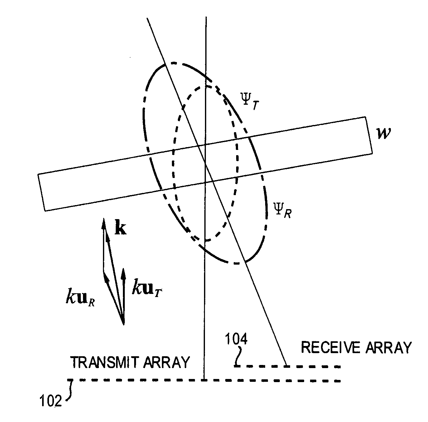
[0025]FIG. 1 is a diagram showing scattering volume weights used in performing the calculations of the preferred embodiment;

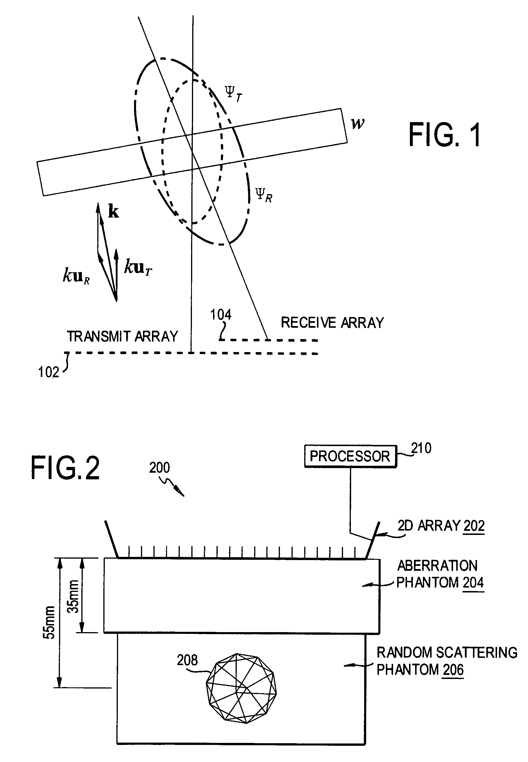
[0026]FIG. 2 is a schematic diagram showing an experimental configuration of the preferred embodiment;

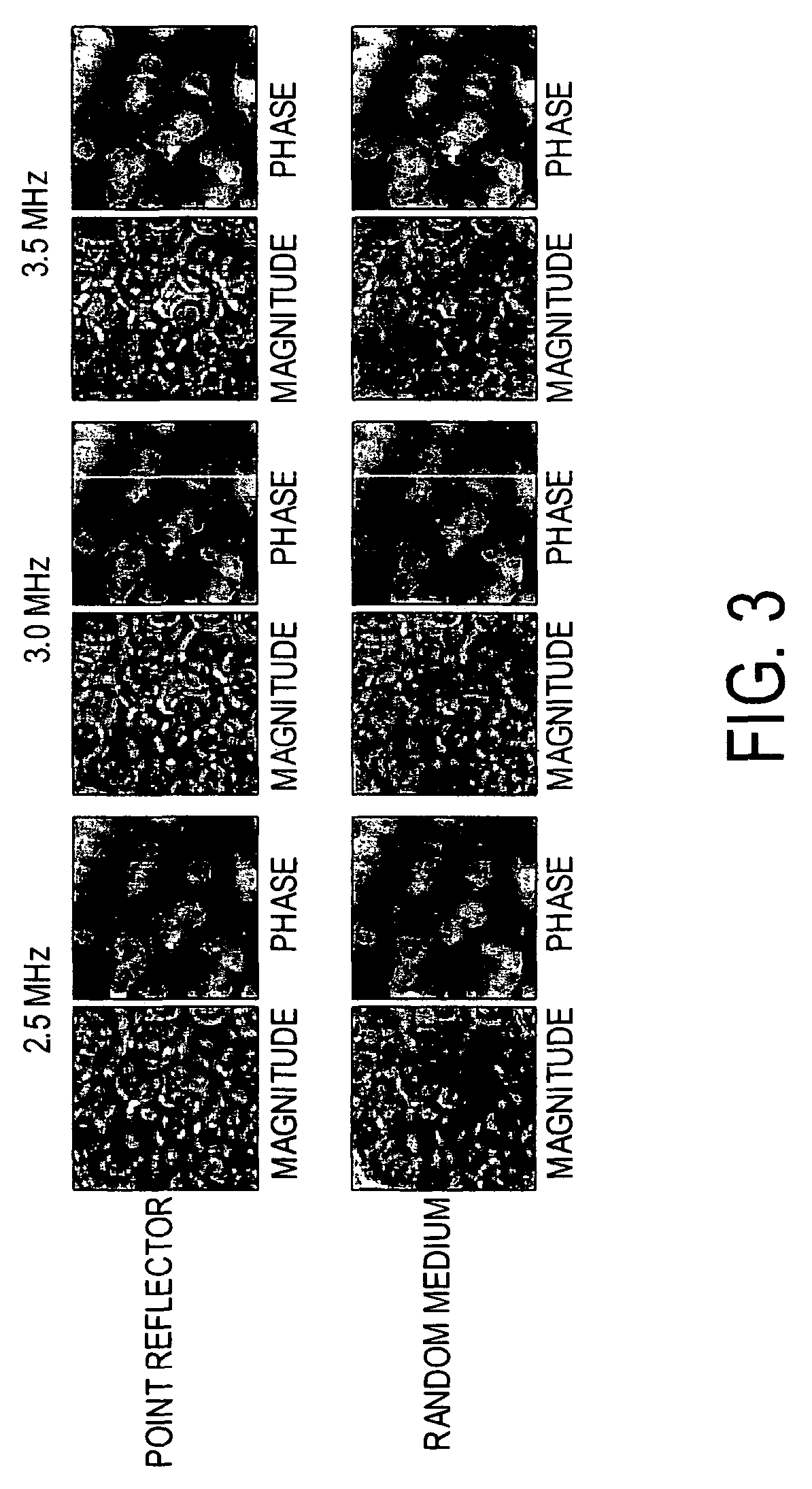
[0027]FIG. 3 is a set of plots of the representative magnitudes and phases of the aberrations estimated according to the preferred embodiment;

[0028]FIG. 4 is a set of plots showing illustrative compensated transmit waveforms;

[0029]FIG. 5 is a set of plots showing representative phase corrected point-reflector and random-medium waveforms;

[0030]FIG. 6 is a set of plots showing a measured transmit focus obtained through a water path and through an aberrator path;

[0031]FIG. 7 is a set of plots showing amplitude projections and effective widths of the transmit-receive focus through a water path and through an aberrator path; and

[0032]FIG...


PUM


Abstract

In estimation of an aberration in propagation of an ultrasonic wave from an aperture through an aberration path, the aperture is modeled as a plurality of sources and receivers. The frequency-domain magnitude of the aberration is estimated by normalizing the scattered signal power spectrum. The frequency-domain phase of the aberration is estimated by a recursion using cross spectra of signals at neighboring receivers.

Description

REFERENCE TO RELATED APPLICATION[0001]The present application claims the benefit of U.S. Provisional Patent Application No. 60 / 591,921, filed Jul. 29, 2004, whose disclosure is hereby incorporated by reference in its entirety into the present disclosure.STATEMENT OF GOVERNMENT INTEREST[0002]The work resulting in the present invention was supported by the National Institutes of Health under Grant Nos. HL50855, CA74050 and EB00280 and the Office of Naval Research under Grant No. N00014-96-1-0749. The government has certain rights in the invention.DESCRIPTION OF RELATED ART[0003]Ultrasound imaging has been the largest growing medical imaging modality in the last fifteen years. Reasons for that are that many disorders can be diagnosed efficiently with ultrasound, the equipment has relatively low cost, and does not require special building adaptations. A promising area for future growth is the market introduction of portable ultrasound imaging equipment. Ultrasound imaging is also widely...

Claims


Application Information

Patent Timeline
Patent Type & Authority Patents(United States)
IPC IPC(8): A61B8/00
CPCG01S7/52049G01S15/8977
Inventor WAAG, ROBERT C.ASTHEIMER, JEFFREY P.
Owner THE UNITED STATES OF AMERICA AS REPRESENTED BY THE SECRETARY OF THE NAVY
Learn More