Method for measurment of network path capacity with minimum delay difference

a network path and delay difference technology, applied in the field of network path capacity measurement, can solve the problems of long time for obtaining a capacity, difficulty in measuring capacity, adverse effects on accuracy and speed, etc., and achieve the effect of less storage and computation, less probe packets, and more effective utilization

Active Publication Date: 2011-06-02
THE HONG KONG POLYTECHNIC UNIV
View PDF7 Cites 19 Cited by
  • Summary
  • Abstract
  • Description
  • Claims
  • Application Information

AI Technical Summary

Benefits of technology

[0017]As the second important aspect of the present invention, the information in the probes is utilized more effectively, and less storage and computation are required for the measurement. By exploiting useful information in a single packet (which is discarded by the MDSUM method), the present invention could send less probe packets for obtaining sufficiently accurate capacity estimates. Moreover, the present invention requires a measuring node to retain only two minimum RTTs and to run a very simple minimum RTT update. In contrast, the PPD-based methods and filtering methods require more storage and computation. For example, the MDSUM filtering method is required to keep track of the minimum delay sum, the minimum delays for the first and second probe packets; and performs a validation test for each measurement. Moreover, it needs to store the packet-pair dispersion sample responsible for the minimum delay sum.
[0018]As the third important aspect of the present invention, the measurement accuracy is more resilient to the impact of cross traffic on the path. When the cross-traffic interference is high, it is easier for the present invention to obtain accurate capacity measurement than the MDSUM filtering method, because the probability of obtaining two minimum delays from different packet pairs is higher than that of obtaining two minimum delays from the same pair. When the cross traffic is low, both the present invention and the MDSUM filtering method obtain accurate capacity estimates. However, the present invention can obtain accurate capacity estimate faster than the MDSUM filtering method.

Problems solved by technology

Capacity measurement is a challenging task in practice, because the accuracy and speed can be adversely affected by cross traffic present on the path.
As a result, a large number of measurements are conducted for each hop and for the entire path, thus requiring a long time for obtaining a capacity estimate and introducing a significant amount of measurement traffic to the network path.
The accuracy and speed of the PPD technique, however, could be seriously degraded by the cross traffic present on the path under measurement.
However, the existing cross-traffic filtering techniques still suffer from slow speed and inefficiencies.
Moreover, injecting a large amount of probe traffic unnecessarily not only prolongs the estimation process, but also affects the normal traffic and introduces additional processing burdens to both the measuring and remote nodes.
The Bprobe measurement can be very slow, because it requires several phases with different probe sizes before arriving at the capacity estimation.
The SProbe's two filtering heuristics are very limited in practical applications.
This cross traffic could delay the first packet to the extent that the dispersion is compressed, causing a capacity overestimation.
This cross traffic could increase the second packet's queueing delay, thus causing a capacity underestimation.
The drawback of the MDSUM technique is that it considers only the packet pair whose packets are both unaffected by cross traffic.
As a result, useful information in those packet pairs is not fully utilized to speed up the measurement process.
Using smaller bins would require a higher number of probe pairs, thus resulting in increasing either the average probing rate (thus the intrusiveness to the network) or time for obtaining the capacity estimate.
Besides introducing a significant amount of probe traffic, another notable problem with the PTD technique is that as the trunk length increases, it is more likely for the packet train to be affected by cross traffic.

Method used


Image

  • Method for measurment of network path capacity with minimum delay difference
  • Method for measurment of network path capacity with minimum delay difference
  • Method for measurment of network path capacity with minimum delay difference

Examples


Embodiment Construction

An Overview

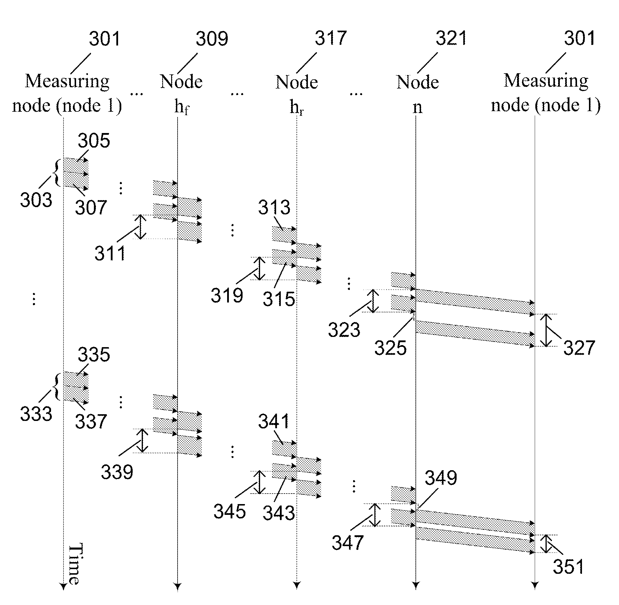
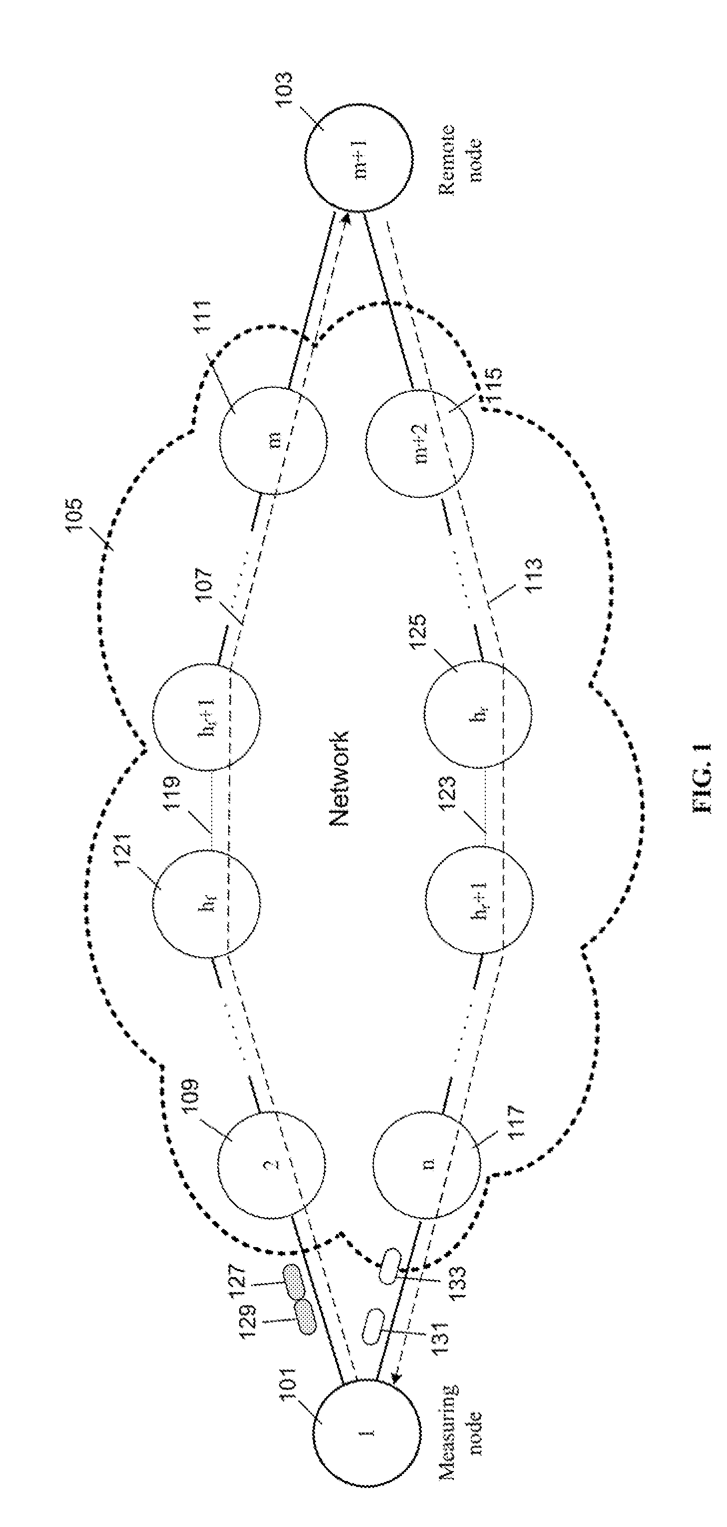
[0036]FIG. 1 is a block diagram illustrating a particular embodiment in accordance with the present invention. It comprises a measuring node 101 and a remote node 103. The measuring node 101 sends two back-to-back probe packets 127 and 129 to the remote node 103 through a network 105 which usually includes multiple hops (such as, routers and switches). The remote node 103, in response to receiving 127 and 129, sends two response packets 131 and 133 to 101. There are n (where n≧4) nodes on the forward path 107 and the reverse path 113, including 101 and 103. The measuring node 101 first sends the probe packets to network node 109, and network node m 111 (where 1≦m127 and 129 to the remote node 103. In response to receiving 127 and 129, the remote node sends the response packets 131 and 133 to network node M+2 115 and network node n 117 subsequently forwards the response packets 131 and 133 to the measuring node 101.

[0037]The forward path 107 and reverse path 113 together c...


PUM


Abstract

A method for achieving fast and efficient measurement of path capacity of a communication network. The method includes the following steps: (a) transmitting a number of probes from a local endpoint to a remote endpoint over a network path and each probe contains at least two outgoing packets and each probe can elicit at least two response packets from the remote endpoint; (b) determining a first minDelay by measuring RTT between the time sending the first probe packet and the time receiving the first response packet; (c) determining a second minDelay by measuring RTT between the time sending the second probe packet and the time receiving the second response packet; and (d) determining a minimum delay difference by subtracting said first minDelay from said second minDelay. The minimum delay difference divided by packet size can be used as a measurement of the network path capacity.

Description

FIELD OF THE INVENTION[0001]The present invention relates to a method of measuring network capacity of a path in communications networks. Particularly, it relates to a method and apparatus for achieving fast and efficient capacity measurement.BACKGROUND OF THE INVENTION[0002]Knowing network capacity is useful for many network applications to improve their performance. Network capacity (or bottleneck bandwidth) refers to the smallest transmission rate of a set of network links, forming a network path from a source to a destination. Existing tools for capacity measurement are mostly based on active methods: they inject probe packets to the network path under measurement. Capacity measurement is a challenging task in practice, because the accuracy and speed can be adversely affected by cross traffic present on the path. The cross traffic is the network traffic other than the traffic introduced by a capacity measurement method. Moreover, it is preferred to minimize the amount of overhea...

Claims


Application Information

Patent Timeline
Patent Type & Authority Applications(United States)
IPC IPC(8): H04L12/26
CPCH04L43/12H04L43/0864
Inventor CHAN, EDMOND W.W.LUO, XIAPUCHANG, ROCKY K.C.
Owner THE HONG KONG POLYTECHNIC UNIV
Why Eureka
Try Eureka