Designed porosity materials in nuclear reactor components

a nuclear reactor and porosity technology, applied in nuclear elements, nuclear engineering, greenhouse gas reduction, etc., can solve the problems of large voids in the lattice structure, large damage, and extremely harsh environment so as to improve the heat conduction effect, increase the efficiency of the nuclear reactor, and increase the gas pressure

Active Publication Date: 2015-03-05
UCHICAGO ARGONNE LLC
View PDF8 Cites 7 Cited by
  • Summary
  • Abstract
  • Description
  • Claims
  • Application Information

AI Technical Summary

Benefits of technology

[0021]Another object of the present invention is to increase the efficiency of nuclear reactors. A feature of the use of porous support materials for nuclear fuel. An advantage of the invention is that the pores provide a means for efficient gas venting from the fuel and perhaps out of the cladding. This controlled release of gas which develops during nuclear fuel use, prevent expansions of the fuel and / or the cladding due to increased gas pressure.
[0022]Still another object of the present invention is to provide an alternative to sintered uranium dioxide fuel pellets. A feature of the present invention is that atomic layer deposition of fuel allows for other uranium compounds to be utilized. An advantage is that these other uranium compounds provide better heat conduction, thereby increasing the safety and efficiency of the reactor core.
[0023]Yet another object of the present invention is to increase the usable life of nuclear fuel pellets. A feature of the present invention is that nuclear fuel pellet begins their operational lives near a dynamically stable equilibrium as a result of the designed porosity. An advantage of the present invention is that typical deterioration of material properties of the pellets and cladding is minimized, thereby leading to extended life cycles of the fuel.
[0024]Yet another object of the present invention is to reduce the waste of nuclear fuel materials. A feature of the present invention is a more complete use of fissile materials. An advantage of the present invention is that less fuel materials are needed and less spent nuclear fuel materials have to be stored.
[0025]Yet another object of the present invention is to provide a more efficient fuel pellet with a longer operational life that can be used in currently operating nuclear reactors. A feature of the present invention is that the fuel pellets are the same size and offer the same amount of heat as currently available sintered fuel pellets. An advantage of the present invention is that currently operating reactors do not need to be retrofitted in order to accommodate the presently invented fuel pellets.
[0026]Yet another object of the present invention is to provide a silicon carbide (SiC) cladding material for use with nuclear fuel scenarios. A feature of the present invention is the resistance to extreme environments, including temperature resistance, corrosion resistance, oxidation resistance, and a resistance to hydrogen embrittlement. An advantage of the present invention is that SiC cladding can withstand rapid water cooling, which takes place when the reactor core overheats.

Problems solved by technology

The inside of a nuclear reactor is an extremely harsh environment.
Not only are materials subject to temperatures as high as 1800° C. at the center of the fuel pellet and to highly corrosive steam, but they are also subject to damage from neutron bombardment.
These displacements lead to the agglomeration of defects, which can create large voids in the lattice structure.
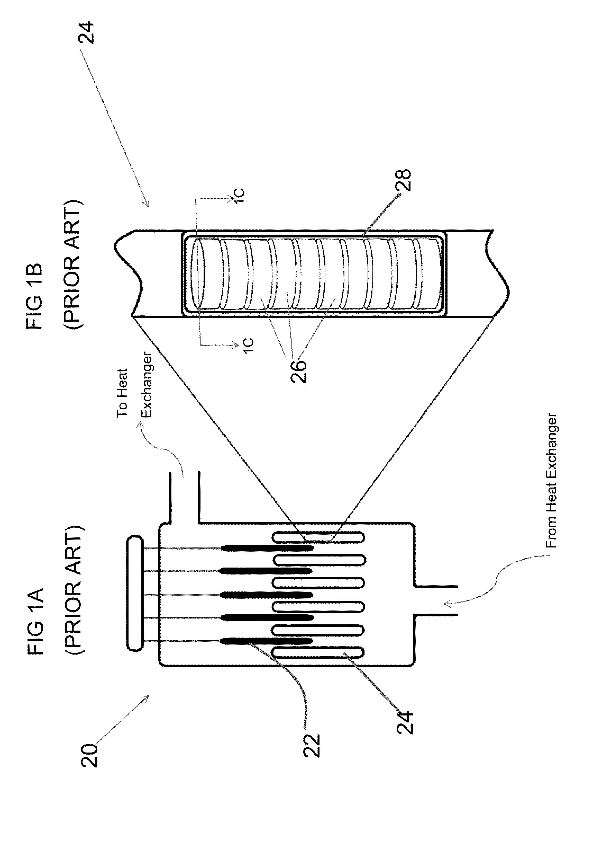
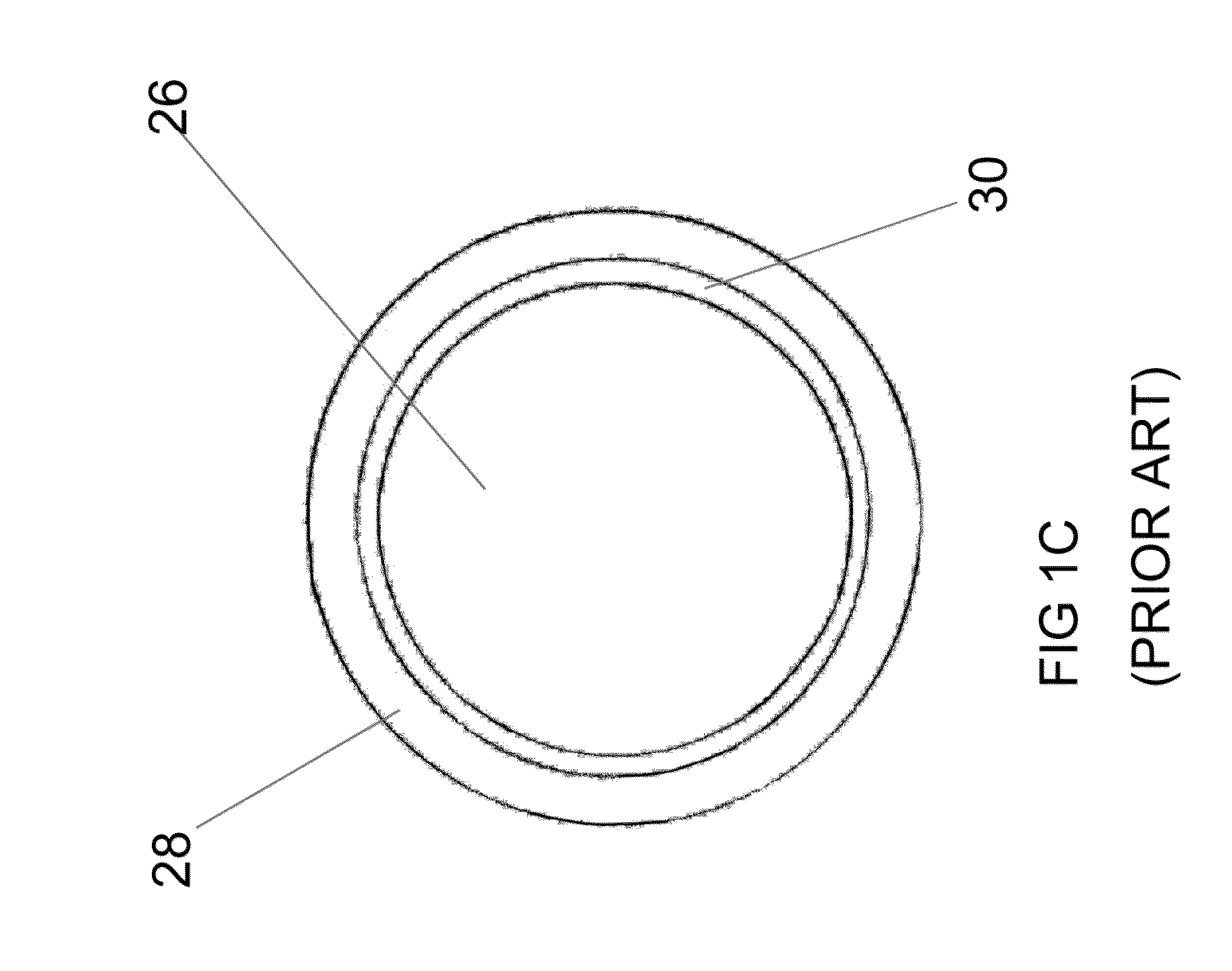
Further, the cladding 28 can no longer be trusted to contain the nuclear fuel.
Meltdown, in particular, can lead to a severe breach of containment.
However, zirconium is prone to hydrogen embrittlement at high-temperatures, especially after a loss-of-coolant-accident (LOCA).
Not only does the presence of hydrogen gas increase the risk of an explosion, but it causes hydrogen embrittlement.
Therefore, not only is much of the fuel wasted, but it also must be carefully stored.
The heat conduction of uranium dioxide is poor relative to that of the cladding material.
Further, such a cladding should have a long operational life.

Method used


Image

  • Designed porosity materials in nuclear reactor components
  • Designed porosity materials in nuclear reactor components
  • Designed porosity materials in nuclear reactor components

Examples


Embodiment Construction

[0041]The foregoing summary, as well as the following detailed description of certain embodiments of the present invention, will be better understood when read in conjunction with the appended drawings.

[0042]As used herein, an element step recited in the singular and preceded with the word “a” or “an” should be understood as not excluding plural said elements or steps, unless such exclusion is explicitly stated. Furthermore, the references to “one embodiment” of the present invention are not intended to be interpreted as excluding the existence of additional embodiments that also incorporate the recited features. Moreover, unless explicitly stated to the contrary, embodiments “comprising” or “having” an element or a plurality of elements having a particular property may include additional such elements not having that property.

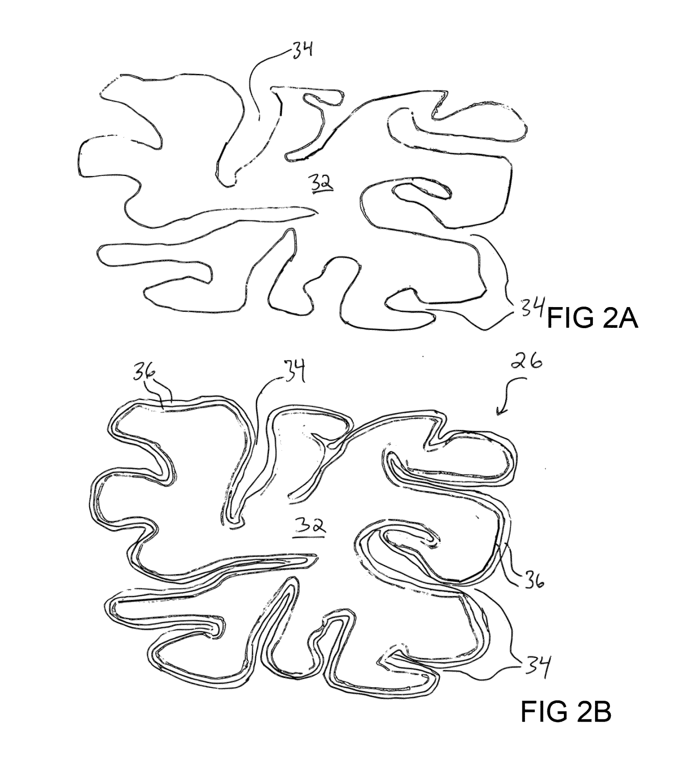
[0043]The invented method imparts size selected porosity to substrates which are subsequently overlayed by adherent film comprising nuclear fuel. This enginee...


PUM

PropertyMeasurementUnit
temperaturesaaaaaaaaaa
temperatureaaaaaaaaaa
distanceaaaaaaaaaa

Abstract

A nuclear fuel pellet with a porous substrate, such as a carbon or tungsten aerogel, on which at least one layer of a fuel containing material is deposited via atomic layer deposition, and wherein the layer deposition is controlled to prevent agglomeration of defects. Further, a method of fabricating a nuclear fuel pellet, wherein the method features the steps of selecting a porous substrate, depositing at least one layer of a fuel containing material, and terminating the deposition when the desired porosity is achieved. Also provided is a nuclear reactor fuel cladding made of a porous substrate, such as silicon carbide aerogel or silicon carbide cloth, upon which layers of silicon carbide are deposited.

Description

CONTRACTUAL ORIGIN OF THE INVENTION[0001]The United States Government has rights to this invention pursuant to Contract No. DE-AC02-06CH11357 between the United States Government and UChicago Argonne, LLC representing Argonne National Laboratory.BACKGROUND OF THE INVENTION[0002]1. Field of the Invention[0003]The present invention relates to atomic layer deposition coatings onto porous materials to provide nuclear fuel pellets and claddings of superior mechanical and thermal properties, which will help increase such components' operational life and improve the efficiency and safety of current light water nuclear reactors.[0004]2. Background of the Invention[0005]The inside of a nuclear reactor is an extremely harsh environment. Not only are materials subject to temperatures as high as 1800° C. at the center of the fuel pellet and to highly corrosive steam, but they are also subject to damage from neutron bombardment.[0006]Neutrons cause fission reactions in typical Light Water Reacto...

Claims


Application Information

Patent Timeline
Patent Type & Authority Applications(United States)
IPC IPC(8): G21C3/18G21C21/02
CPCG21C21/02G21C3/18G21C3/044G21C3/045G21C3/07G21C3/20Y02E30/30
Inventor YACOUT, A. M.PELLIN, MICHAEL J.STAN, MARIUS
Owner UCHICAGO ARGONNE LLC
Why Eureka
Try Eureka