Fluid machine for rankine cycle

a technology of rankine apparatus and flue, which is applied in the direction of positive displacement liquid engine, liquid degasification, separation process, etc., can solve the problems of increasing the connection portions difficult to apply the rankine apparatus to a vehicle, and increasing the structure of the rankine apparatus. , to achieve the effect of safely and surely stopping the expansion device and easy equalizing the pressur

Inactive Publication Date: 2011-01-18
DENSO CORP +1
View PDF17 Cites 3 Cited by
  • Summary
  • Abstract
  • Description
  • Claims
  • Application Information

AI Technical Summary

Benefits of technology

[0018]It is another object of the present invention to provide a fluid machine, according to which lubricating oil is pooled in a housing, the viscosity of the lubricating oil in increased, and the lubricating oil is surely supplied to sliding portions.
[0019]It is a further object of the present invention to provide a fluid machine, which is simple in structure for pressurizing sucked working fluid and pumping out, and for surely lubricating sliding portions.
[0020]It is still a further object of the present invention to provide an expansion device and a control device thereof, according to which working fluid bypassed by a bypass device according to necessity, and which is advantageous in its mounting performance and cost.
[0026]As above, the oil storing chamber is so formed as to cover the contacting portions of the driving shaft, which are in contact with the ring shaped piston and the bearings. The smooth lubrication at the sliding portions is assured by filling the oil storing chamber with the lubricating oil of the high viscosity. In addition, the small spaces are formed at the axial side surfaces of the ring shaped piston and at the outer side of the oil storing chamber, wherein the pressure in the small spaces is held at such a pressure lower than the pressure in the oil storing chamber. As a result, the working fluid of the low viscosity, which flows from the pump chamber formed in the cylinder chamber to the axial side surfaces of the ring shaped piston, is collected in the small spaces, so that the working fluid is prevented from flowing into the oil storing chamber. Finally, it is avoided that the lubricated oil in the oil storing chamber is diluted and the diluted lubricating oil blocks the formation of the oil film at the sliding portions.
[0027]It is possible to structure the small spaces, the pressure of which is held at the pressure lower than that in the oil storing chamber, without increasing the number of parts and assembling steps. Accordingly, the lubrication at the sliding portions can be surely carried out by a simple structure, in which the oil storing chamber and the small spaces are formed.
[0029]As above, the expansion device is realized, in which it is possible for the working fluid to bypass the driven portion by opening the switching device according to need. Namely, it is possible in the expansion device to easily equalize the pressure between the high pressure chamber and the low pressure portion, so that it becomes possible to safely and surely stop the expansion device. The communication port and the switching device are provided within the space of the housing. Therefore, the external pipe arrangement, as is necessary in the prior art, is not necessary, and in addition the expansion device of the invention is advantageous in its mounting performance and cost.

Problems solved by technology

Accordingly, the structure for the Rankine apparatus becomes more complicated and connecting portions in the Rankine apparatus are increased.
As a result, it is hard to apply the Rankine apparatus to a vehicle, in which mounting condition is strict.
Therefore, it is difficult to pool the lubricating oil at the lower portion of the space for the electric rotating device.
As a result, a sufficient amount for a thickness of an oil film may be hardly obtained at the sliding portions.
However, the above fluid machine has a complicated structure, and therefore, it is a problem in increase of the number of parts and increase of assembling steps, when the small diameter shaft portions are formed at the eccentric shaft portion and annular grooves are formed at the large diameter shaft portion to provide therein the seal members.
As a result, sufficient lubrication at the sliding portions may not be achieved.
However, when the bypass passage is provided as in the apparatus of the above mentioned Japanese Patent Publication, a performance for mounting the apparatus in a limited space is deteriorated and cost for the bypass passage is increased, because the bypass passage is provided at the outside of the expansion device.

Method used


Image

  • Fluid machine for rankine cycle
  • Fluid machine for rankine cycle
  • Fluid machine for rankine cycle

Examples


first embodiment

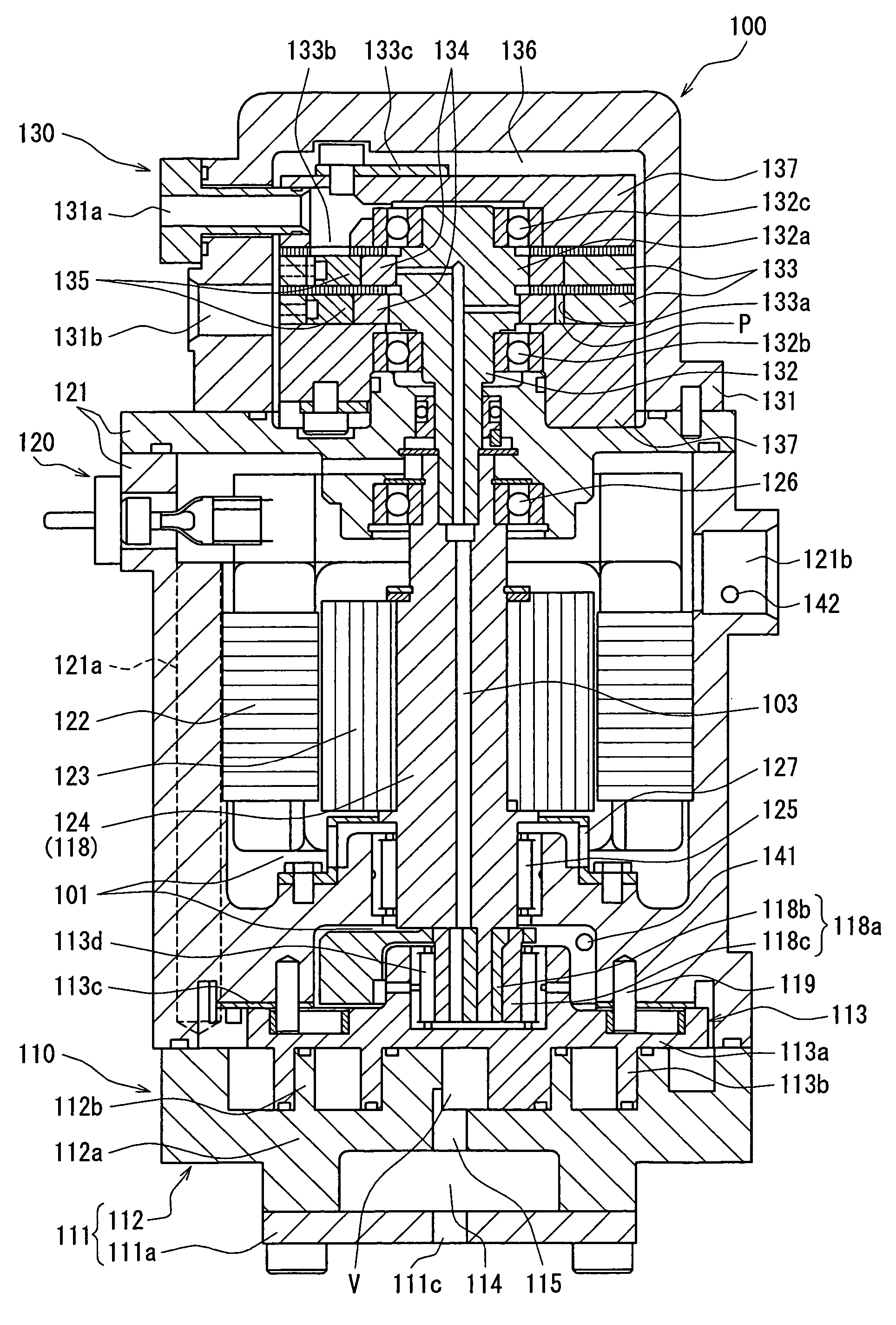
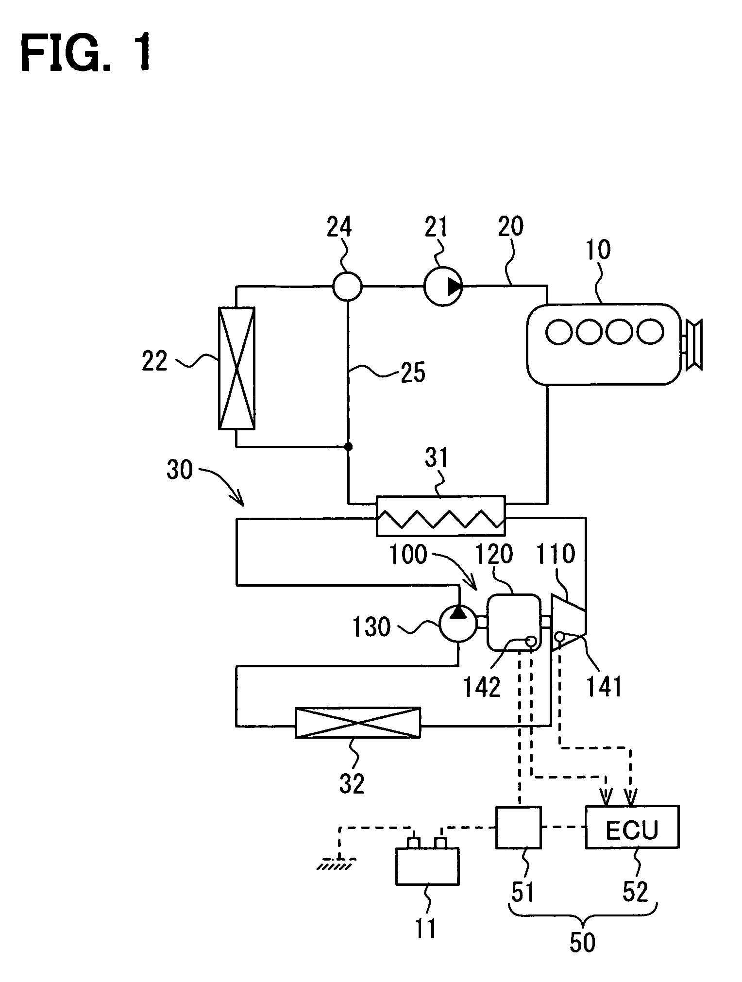
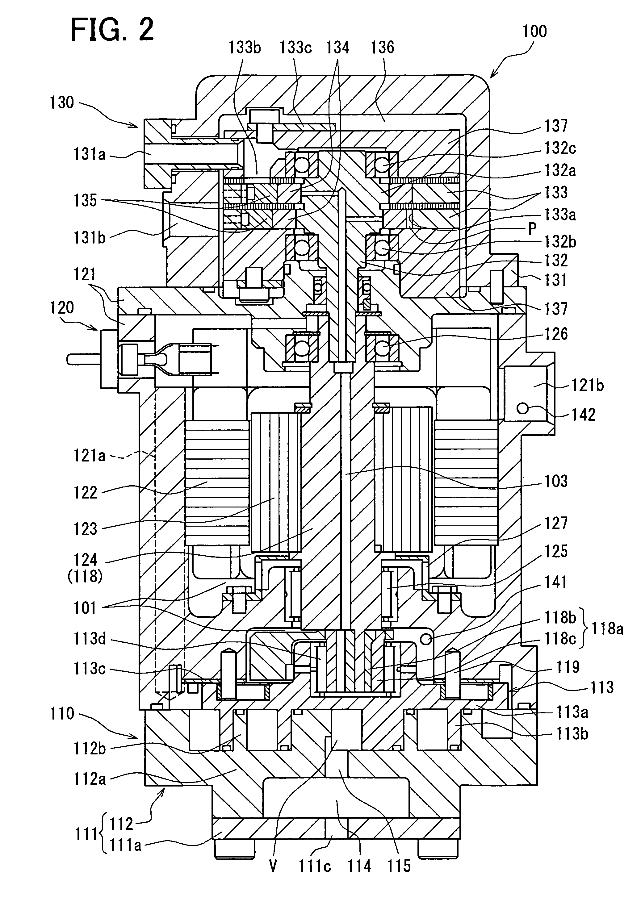
[0062]In a first embodiment, a fluid machine is formed as such a device 100 integrally having a refrigerant pump, an expansion device and an electric power generator (hereinafter also referred to a pump-expansion-generator device). The pump-expansion-generator device 100 is applied to Rankine cycle 30 for a vehicle. The pump-expansion-generator device 100 comprises the expansion device (i.e. an expansion portion of the present invention) 110, a motor generator (i.e. the electric power generator of the present invention) 120 as an electric motor and as the electric power generator, and the refrigerant pump 130, wherein those components are integrally formed. A system structure will be explained hereinafter with reference FIG. 1.

[0063]The Rankine cycle collects energy (as a driving force generated at the expansion device 110) from waste heat generated at an engine 10 (i.e. an external heat energy source of the present invention). The Rankine cycle is formed by the refrigerant pump 130...

second embodiment

[0114]A second embodiment of the present invention is shown in FIG. 7. In the second embodiment, a control (a control flow) before starting up the Rankine cycle 30 is different from that for the first embodiment.

[0115]In the control flow of the second embodiment, the steps S130 and S150 of the first embodiment (FIG. 3) are eliminated. Namely, when the controller 52 determines at the step S120 that the viscosity of the lubricating oil is lower than the predetermined viscosity, the controller 52 outputs a command signal at the step S140 for the current supply to the stator 122 so as to heat the refrigerant in the oil pooling portions 101, without calculating the current supply period to the stator 122 of the motor generator 120. The process goes back to the step S100 to detect the temperature and the pressure of the refrigerant by the temperature sensor 141 and the pressure sensor 142. In the case that the viscosity of the lubricating oil becomes higher than the predetermined viscosit...

third embodiment

[0117]A third embodiment of the present invention is shown in FIG. 8. In the third embodiment, a heating unit for heating the refrigerant in the oil pooling portions 101 is modified, when compared with the first embodiment.

[0118]A water jacket 151 is provided at an outer peripheral portion of the motor housing 121, and a bypass passage 151a is connected to the water jacket 151, wherein the bypass passage 151a bypasses the heating device 31. The water jacket 151 and the bypass passage 151a correspond to a heat medium passage to form the heating unit. An on-off valve 151b is provided at the bypass passage 151a, wherein the on-off valve is controlled by the controller 52 for opening or closing the passage.

[0119]According to the third embodiment, the controller 52 calculates the viscosity of the lubricating oil in the oil pooling portions 101 before the start-up of the Rankine cycle 30 as well as during the normal operation. And the controller 52 opens the on-off valve 151b so that the ...


PUM

PropertyMeasurementUnit
currentaaaaaaaaaa
temperatureaaaaaaaaaa

Abstract

It is an object to provide a fluid machine, which is simple in structure and in which lubricating oil containing smaller amount of the working fluid is supplied to sliding portions of an expansion device. The fluid machine has the expansion device for generating a driving force by expansion of the working fluid, which contains the lubricating oil and is heated to a gas phase condition. The fluid machine further has an electric power generating device driven by the driving force of the expansion device and generating electric power. An oil pooling portion is formed in a fluid passage, through which the working fluid discharged from the expansion device flows, such that the lubricating oil contained in the working fluid is brought into contact with at least one of sliding portions of the expansion device and the electric power generating device. And a heating unit is provided to heat the working fluid in the oil pooling portion.

Description

CROSS REFERENCE TO RELATED APPLICATION[0001]This application is based on Japanese Patent Application Nos. 2005-368519 filed on Dec. 21, 2005, 2006-9107 filed on Jan. 17, 2006, 2006-256073 filed on Sep. 21, 2006, 2006-259437 filed on Sep. 25, 2006, and 2006-55380 filed on Mar. 1, 2006, the disclosures of which are incorporated herein by reference.FIELD OF THE INVENTION[0002]The present invention relates to a fluid machine, which generally includes an expansion device arranged in Rankine cycle having waste heat of an internal combustion engine as its thermal source, an electrical power generating device driven by the expansion device to generate electrical power, and / or a pump for circulating working fluid in the Rankine cycle.BACKGROUND OF THE INVENTION[0003]It is known in the art, as disclosed in Japanese Patent Publication No. S58-32908, that an oil separating device is provided in a Rankine apparatus. A heat exchanger is provided in the oil separating device for supplying heat ene...

Claims


Application Information

Patent Timeline
Patent Type & Authority Patents(United States)
IPC IPC(8): F01K13/02
CPCF01C13/04F01K21/005F01K25/04F01K25/06F01C1/0215F04C2240/45
Inventor UNO, KEIICHIASA, HIRONORITAKEUCHI, YASUHIROOGAWA, HIROSHIKISHITA, HIROSHIUCHIDA, KAZUHIDEKAWASE, YASUHIROINABA, ATSUSHI
Owner DENSO CORP
Why Eureka
Try Eureka