Sliding window magnetic electrical connector

a magnetic electrical connector and sliding window technology, applied in the direction of coupling device details, coupling device connections, electric discharge lamps, etc., can solve problems such as electrical circuit breakage, and achieve the effect of preventing accidental contact and reliable power supply

Inactive Publication Date: 2011-01-18
CASCO PRODUCTOS CORP
View PDF17 Cites 53 Cited by
  • Summary
  • Abstract
  • Description
  • Claims
  • Application Information

AI Technical Summary

Benefits of technology

[0009]An aspect of the invention is that the enclosure for the movable carriage in the stationary connector part is movable or floats in the stationary connector part housing. This allows limited movement of the enclosure and the external contact or contacts of the stationary connector part so that they can compensate for tolerances in the mounting positions of the stationary and movable connector parts in at least two dimensions. For example, the floating enclosure allows the external contact or contacts to maintain alignment with the contact or contacts of the movable connector part despite manufacturing tolerances, for example, in the glass and frame parts to which the connector parts are mounted.
[0010]The invention allows for reliably providing power to the sliding glass rear window defroster and prevents any accidental contact with the vehicles's electrical system power when the window is open and the external contact or contacts of the stationary connector part are exposed.

Problems solved by technology

When the sliding glass is opened, the electrical circuit is broken but the exposed terminals on the stationary connector part, which provide the electrical power, are not supplied with electrical power due to a magnetic switching element contained within the stationary connector part.

Method used


Image

  • Sliding window magnetic electrical connector
  • Sliding window magnetic electrical connector
  • Sliding window magnetic electrical connector

Examples


Embodiment Construction

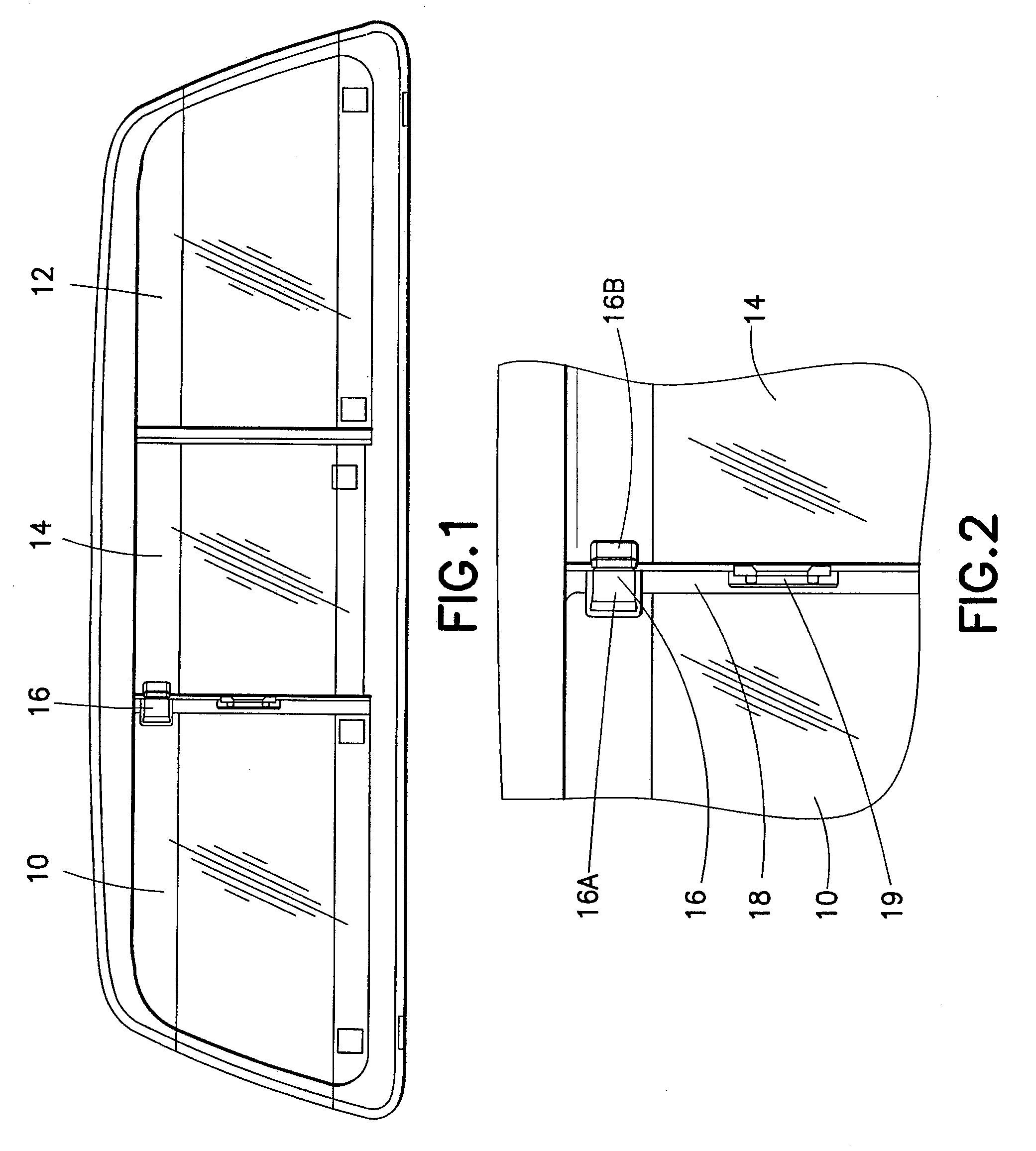
[0040]With reference now to the drawings, FIG. 1 shows a rear window for a motor vehicle, in particular, for a pick-up truck. The rear window includes a first stationary portion 10, a second stationary portion 12 and a slidable portion 14. The slidable portion 14 is designed to slide to the right in the example shown in FIG. 1. The portion 14 is adapted to slide in tracks provided at the bottom and top of the frame of the window. Typically, a latch 19 on frame part 18 is provided to open and latch the window closed (FIG. 2).

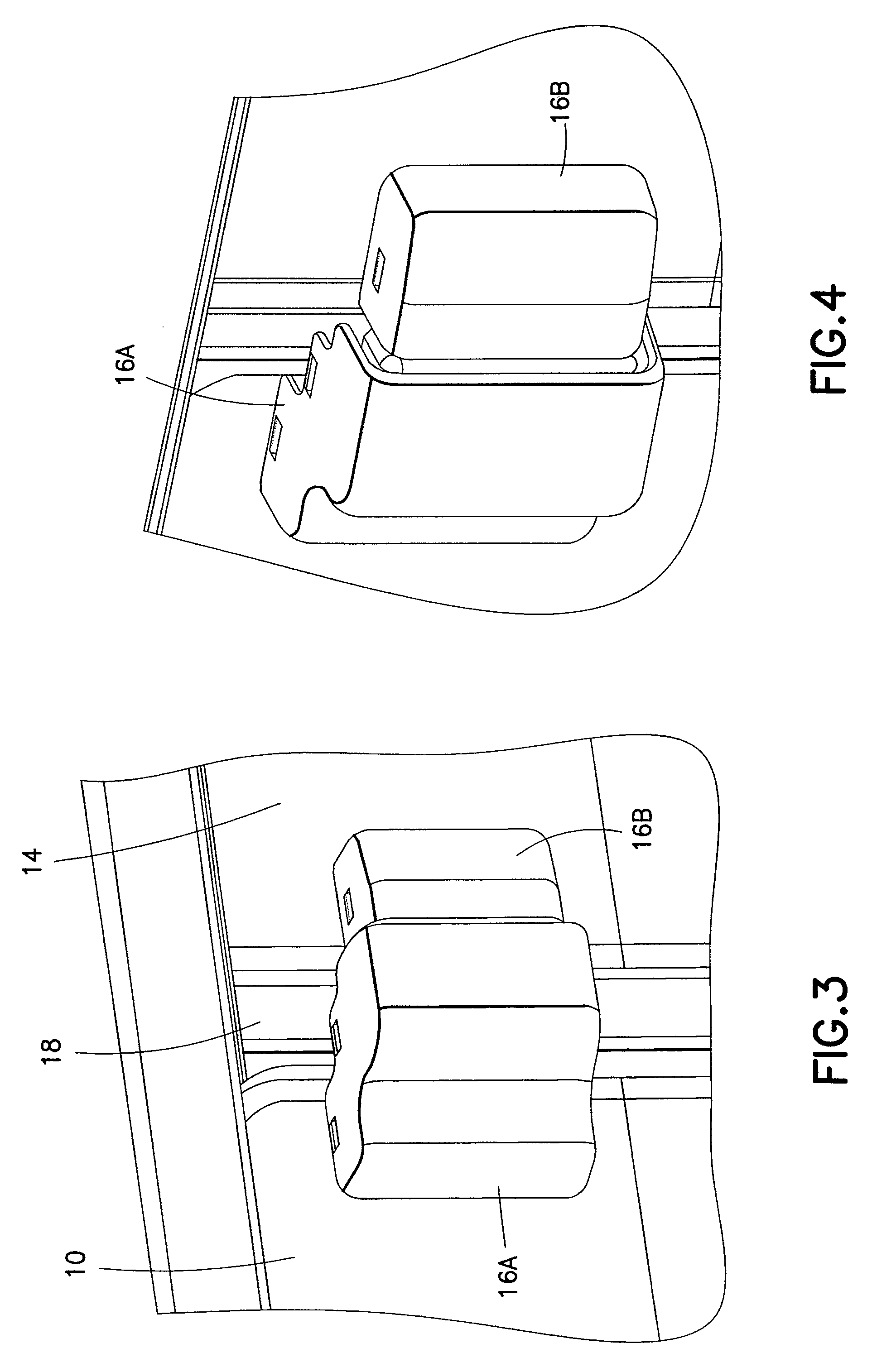
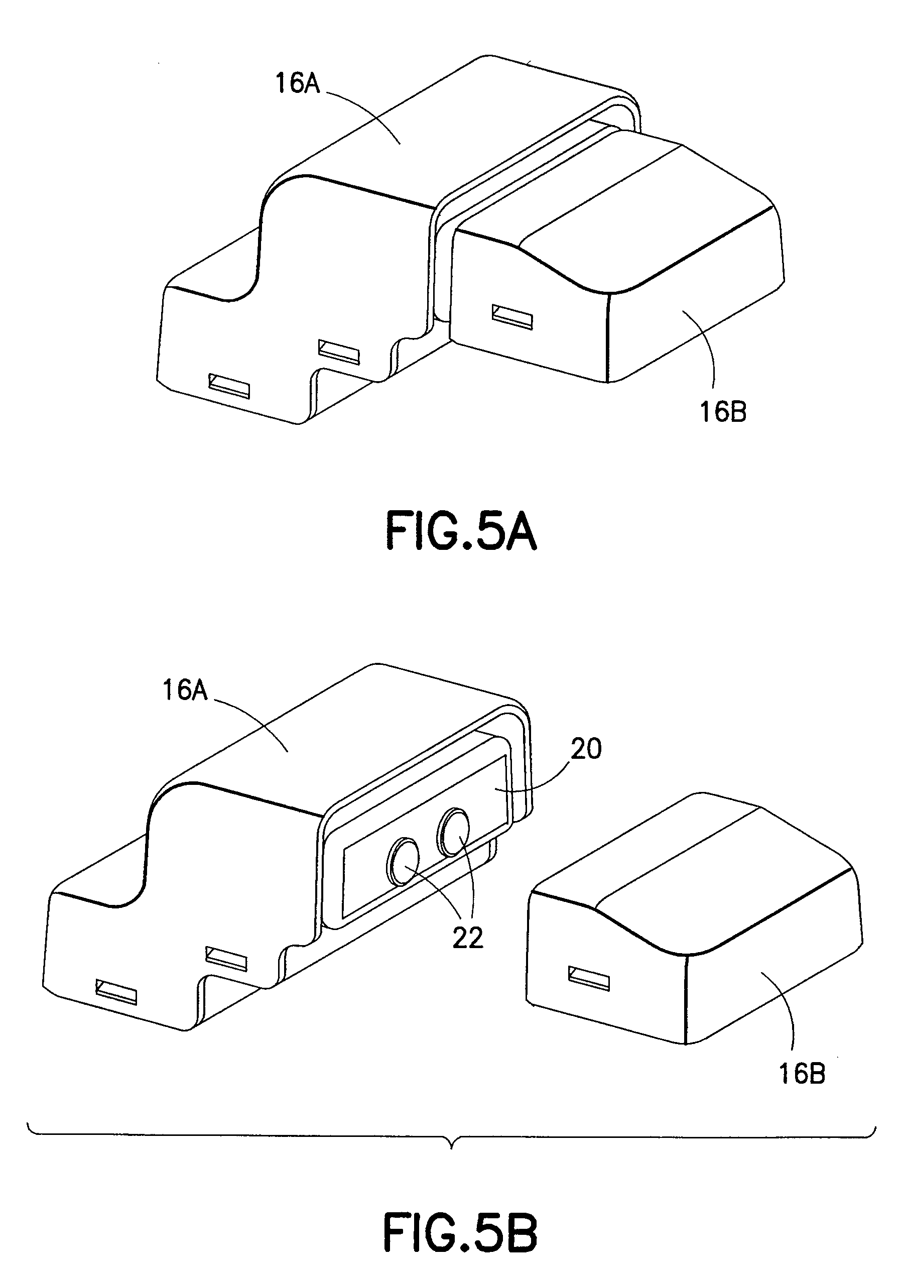
[0041]A connector, shown generally at 16, the detail of which is shown in FIG. 2, is provided according to the invention. The connector includes a stationary part 16A and a slidable connector part 16B. The stationary part 16A is mounted to the glass 10 and / or the stationary glass frame, or both. The slidable connector part 16B is mounted to the slidable glass portion 14 or its frame, or both. The parts 16A and 16B can be mounted using an adhesive or double sided ...


PUM


Abstract

An electrical connector for supplying electrical power from a fixed member to a movable member that moves with respect to the fixed member, the movable member bearing an electrical load. The electrical connector has a first connector part fixed to the fixed member and connected to a source of electrical power. A second connector part is fixed to the movable member and is connected to the electrical load. The first connector part and second connector part are movable into electrical engagement when the movable member is moved adjacent the fixed member. The first connector part has a first housing, a movable enclosure in the housing, having first external electrical contacts, and a movable carriage bearing second electrical contacts. The movable carriage has first magnets or magnet attractive components, the second contacts being movable with the carriage by a first magnetic force into electrical engagement with the first contacts.

Description

BACKGROUND OF THE INVENTION[0001]The present invention relates to electrical connectors, and in particular, to a movable window electrical connector for providing electrical power to an electrical load mounted on the movable window, e.g., a sliding window. More particularly, the present invention relates to a sliding window electrical connector for an automotive sliding window defroster. Even more particularly, the present invention relates to such an electrical connector for the sliding rear window of pick-up trucks or other vehicles having a sliding window with an electrical defroster mounted on or in the sliding window. More particularly, the invention relates to such a connector that employs a magnetically operated connection and disconnection mechanism.[0002]Some vehicles, in particular, pick-up trucks and other trucks, often have a sliding center rear window part so that the rear window can be opened. This allows ventilation and also allows long objects to be extended from the...

Claims


Application Information

Patent Timeline
Patent Type & Authority Patents(United States)
IPC IPC(8): H01R33/00
CPCH01R13/6205H01R2201/26Y10S439/906
Inventor FIRMAN, II, GARY LEERUTKOWSKI, DAVID J.HOLLAND, GREGORY J.MING, MA
Owner CASCO PRODUCTOS CORP
Why Eureka
Try Eureka