
LED lighting apparatus and method of using same for illumination of a body cavity

a technology of led lighting and body cavity, which is applied in the field of led lighting apparatus and a method of using the same for body cavity illumination, can solve the problems of insufficient overhead lighting, affecting the patient, and insufficient lighting alone in many circumstances

Inactive Publication Date: 2011-01-18
MEDICAL VISION INDS
View PDF22 Cites 14 Cited by
  • Summary
  • Abstract
  • Description
  • Claims
  • Application Information

AI Technical Summary

Benefits of technology

"The present invention provides an LED lighting apparatus and a method of using it for illumination of a body cavity during surgery. The method allows for continuous internal lighting without damaging tissue, and can also provide a plurality of switched LED's for surgical use. The apparatus includes a retractor with LED's that can be elevated or depressed to view the area surrounding the elevated tissue. The technical effects include improved visibility and reduced damage to tissue during surgery."

Problems solved by technology

For instance, it is well known that hospitals spend exorbitant amounts of money to provide surgeons with overhead lighting in surgery.
Nonetheless, in large part to the obstruction in the path of light caused by the physical presence of the surgeon, overhead lighting alone may not, in many circumstances, be adequate.
While these have the advantage of not being obstructed by the physical presence of the surgeon, they introduce other issues, as they can be uncomfortable to wear, and also must have sufficient strength to travel distances of over 2 to 3 feet, from the top of the surgeon's head to the point of interest.
Additionally, such headsets require the surgeon to position their head to direct the light in the appropriate direction, which can be cumbersome.
As a result, during surgical medical procedures that require incisions in order to gain access to a body cavity, incisions must be made sufficiently large in order to allow for the insertion not only of the instruments and the hands of the surgeon, but also for paths of light into the body cavity of interest, which can be detrimental to the patient.
Such insertion, however, requires a pair of hands to direct the light, and known devices do not provide sufficient illumination, both in terms of the area of illumination, as well as amount of light output.

Method used


Image

  • LED lighting apparatus and method of using same for illumination of a body cavity
  • LED lighting apparatus and method of using same for illumination of a body cavity
  • LED lighting apparatus and method of using same for illumination of a body cavity

Examples


Embodiment Construction

The present invention provides LED lighting apparatus and a method of using the same for illumination of a body cavity. While certain aspects of the invention are described in the context of a human body cavity, it will be understood that these aspects are equally applicable to body cavities of animals other than humans.

An embodiment of the LED lighting apparatus according to the present invention will first be described, and then a description of its use, both generally as well as particularly with reference to certain surgical procedures, is provided.

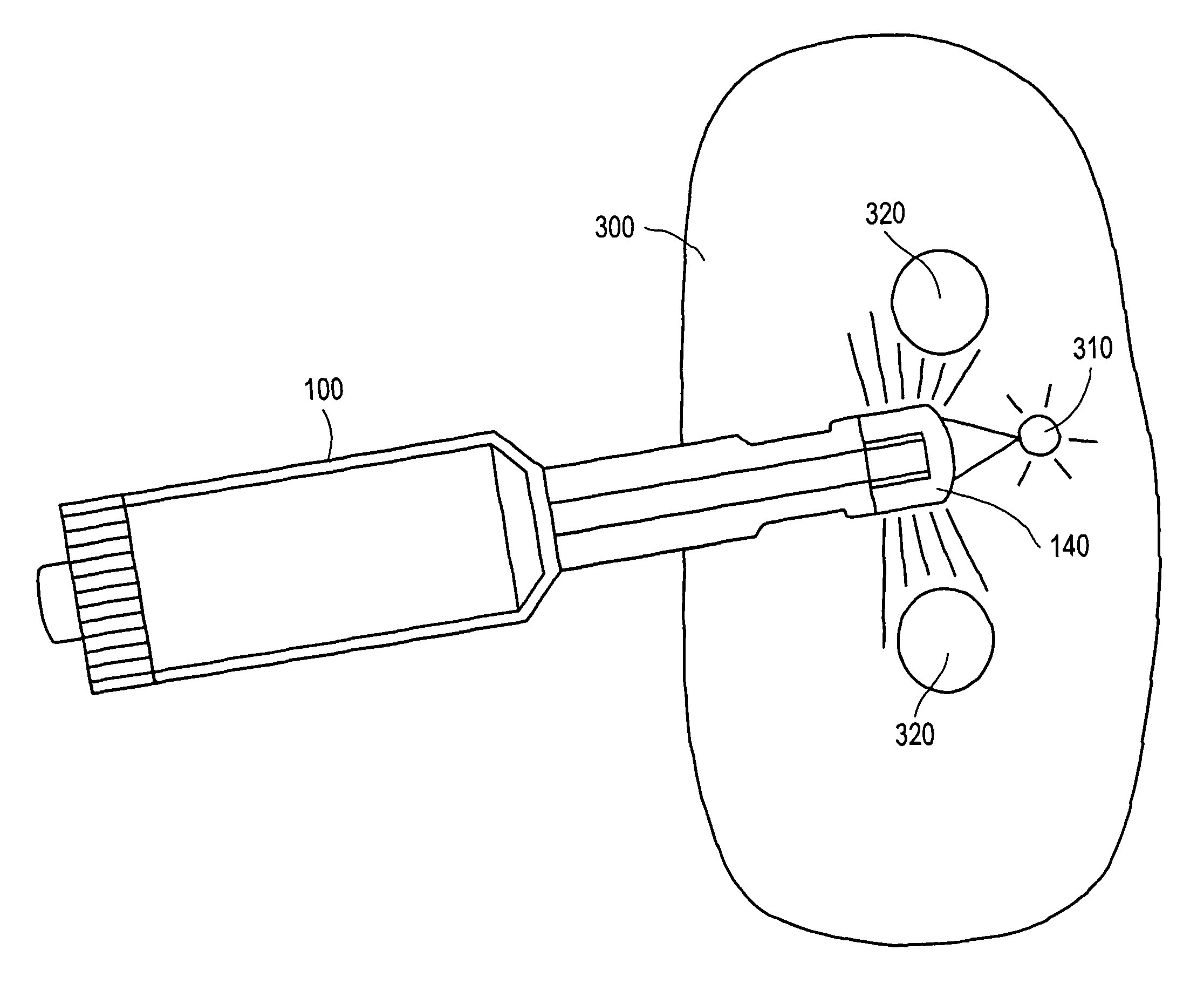
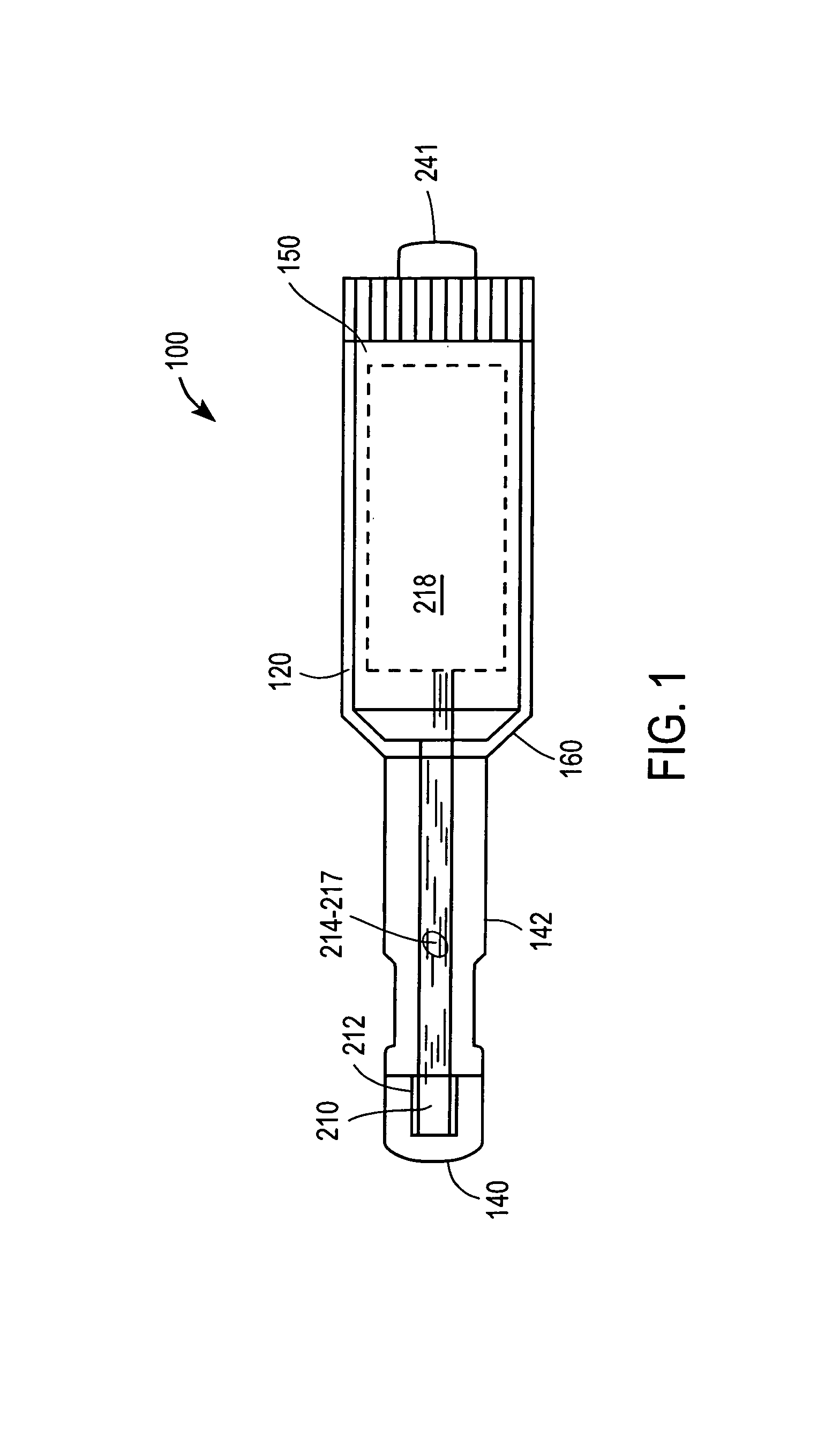
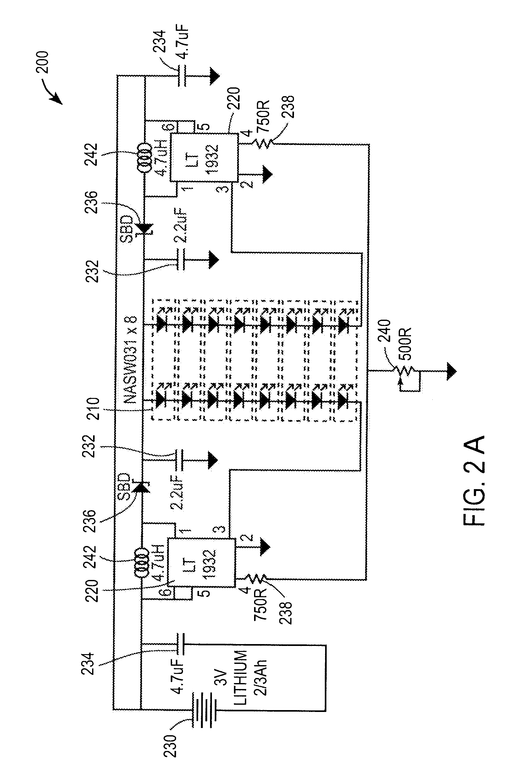
Handheld lighting device 100 contains an electrical lighting circuit 200, preferably fully contained within a housing 120. Light is transmitted radially outward in forward and side direction from an LED array 210 disposed within and at a transparent front tip 140 of the housing 120. The LED array 210 is connected through wires to electrical components that form the remainder of the electrical lighting circuit 200 and are formed within...


PUM


Abstract

The present invention provides an LED lighting apparatus and a method of using the same for illumination of a body cavity. In one aspect, the present invention provides a method of surgery in which one incision is made for hands and surgical instruments, and another incision is made for insertion of an LED lighting device. Both incisions open into the same cavity, and the lighting device provides continuous internal lighting to the body cavity where the operation is occurring. In another aspect, a method and apparatus are described that provide internal chandelier lighting to an internal body cavity using a plurality of switched LED's for surgical without damaging tissue within the body cavity.

Description

BACKGROUND OF THE INVENTION1. Field of the InventionThe present invention relates to an LED lighting apparatus and a method of using the same for illumination of a body cavity, particularly a body cavity that has been exposed during a surgical procedure requiring an incision.2. Background of the InventionThat various medical procedures require light is well known. For instance, it is well known that hospitals spend exorbitant amounts of money to provide surgeons with overhead lighting in surgery. Nonetheless, in large part to the obstruction in the path of light caused by the physical presence of the surgeon, overhead lighting alone may not, in many circumstances, be adequate.External lighting such as light beams worn as a headset is also well known. While these have the advantage of not being obstructed by the physical presence of the surgeon, they introduce other issues, as they can be uncomfortable to wear, and also must have sufficient strength to travel distances of over 2 to 3...

Claims


Application Information

Patent Timeline
Patent Type & Authority Patents(United States)
IPC IPC(8): A61B1/32
CPCA61B1/0676A61B1/0684A61B5/0084A61B19/52A61B2017/00283A61B2019/521A61B90/36A61B2090/309Y10S362/804
Inventor TALIEH, YAHYA JOHN
Owner MEDICAL VISION INDS
Learn More