
Method and adaptive distance protection relay for power transmission lines

a technology of power transmission line and relay, which is applied in the direction of short-circuit testing, fault location, instruments, etc., can solve the problems of inability to accurately consider the compensation of the remote end infeed effect, the method is simplified, and the difficulty of on-line application of protective relaying

Active Publication Date: 2011-01-18
HITACHI ENERGY LTD
View PDF4 Cites 11 Cited by
  • Summary
  • Abstract
  • Description
  • Claims
  • Application Information

AI Technical Summary

Benefits of technology

[0018]The object of the present invention is to solve the problems related to known methods and prior art and to create an improved, simple and reliable method and device for an adaptive distance protection of three-phase power transmission lines.
[0019]A further object is to improve the operation under resistive faults and by reducing underreaching and overreaching of the relay which is caused by a remote line end infeed effect.
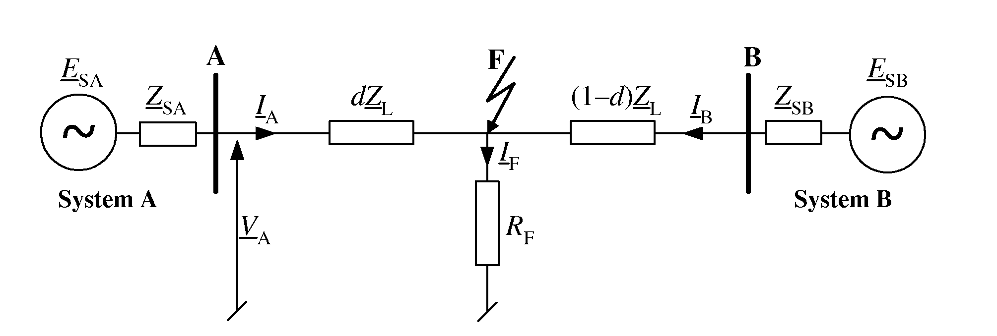
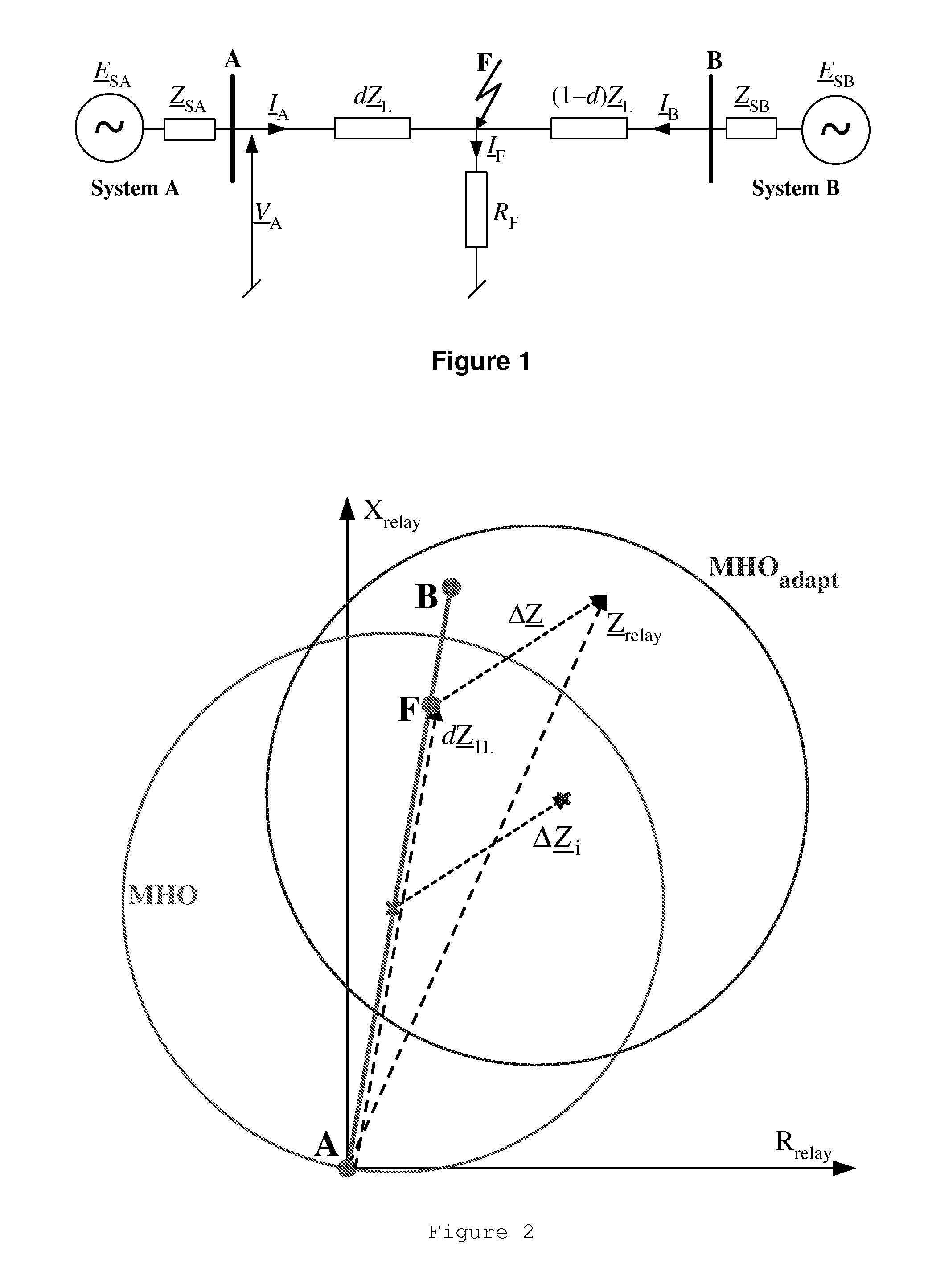
[0025]According to the invention, the fault loop impedance Zrelay is adapted by shifting it in the complex plane along the impedance shift ΔZ, which represents the influence of the fault current IF by taking into account the phase angle γ of the fault current distribution factor kF. Thereby, the method and the adaptive distance protection relay according to the invention compensate for the remote line end infeed effect and increase the accuracy of the determined distance to fault d.
[0035]The invention provides a new digital distance algorithm for both single and parallel power transmission lines. In case of parallel lines, the third solution can be applied which requires providing standard measurements from one end of the parallel lines. An approach which originates initially from fault location aimed at inspection-repair purposes was enhanced to be utilized here for assuring adaptability of a distance relay to the “reactance effect” which is relevant for resistive faults. An improved estimation of the voltage drop across the fault path resistance RF is introduced into the algorithm. As a result of that, determination of the zero sequence currents is avoided and the incremental positive sequence component and the negative sequence component are utilized. In that the provided method differs from known algorithms. The method according to the invention has been tested with the fault data obtained from simulations performed using the known ATP-EMTP software.

Problems solved by technology

The distance to fault is calculated with use of the quadratic equation, which is suitable for the off-line fault location purpose and rather difficult for on-line application to protective relaying.
However, if the remote-end and local zero-sequence contributions are out of phase, an error in the dynamic response would occur.
This means that the method is simplified and does not consider compensation of the remote end infeed effect accurately.
It is worth to notice that performing iterative calculations for the on-line application of protection is rather difficult and in certain conditions the convergence of iterative calculations is not obtained.

Method used


Image

  • Method and adaptive distance protection relay for power transmission lines
  • Method and adaptive distance protection relay for power transmission lines
  • Method and adaptive distance protection relay for power transmission lines

Examples


Embodiment Construction

Remote End Infeed Influence on Distance Relay Operation

[0041]The following explanations relate to the relay A, arranged at the respective position A in the transmission line depicted in FIG. 1.

[0042]According to standard typical distance protection, a fault loop impedance Zrelay is determined from a fault loop voltage Vrelay and a fault loop current Irelay, both composed, according to the current fault type, of measurements of phase voltages or currents, respectively, taken by relay A (see Table 1):

[0043]Z_relay=V_relayI_relay=Rrelay+j⁢⁢Xrelay(1)

[0044]

TABLE 1Composition of relaying signals for different fault typesFault typeRelaying voltage, currentph-gVrelay = Vph,Irelay = Iph + k0I0 + k0mIparallel_0ph1-ph2, ph1-ph2-g,Vrelay = Vph1 −Vph2,ph1-ph2-ph3, ph1-ph2-ph3-gIrelay = Iph1 −Iph2where ph, ph1, ph2, g are subscripts for indicating faulted phasesor ground, respectively;I0, Iparallel_0 are the zero sequence current of the faulted or thehealthy parallel line, respectively;k_0=Z_0⁢L-...


PUM


Abstract

A method and an adaptive distance protection relay for compensating for a remote line end infeed effect during determination of a distance to a resistive fault on a three-phase power transmission line. It is assumed that a fault current flows through the fault resistance. A fault loop impedance is first calculated by a known algorithm from phase voltages and phase currents. A shift of the fault loop impedance is determined from the fault loop impedance, the impedance of the transmission line for the positive current sequence and the phase angle of a complex fault current distribution factor, where the fault current distribution factor is the ratio of the fault loop current to the fault current. The distance to fault is calculated by subtracting the impedance shift from the fault loop impedance and dividing the result by the impedance of the transmission line for the positive current sequence.

Description

CROSS-REFERENCE TO RELATED APPLICATIONS[0001]This application claims priority to Swedish patent application 0600322-2 filed 10 Feb.2006 and is the national phase under 35 U.S.C. §371 of PCT / EP2006 / 070082 filed 21 Dec.2006.TECHNICAL FIELD[0002]This invention relates to a method and a device for an adaptive distance protection of power transmission lines and relates more particularly to a distance protection relay with improved operation under resistive faults, adapted to reduce under-reaching and overreaching of the relay, that is caused by a remote line end infeed effect.BACKGROUND OF THE INVENTION[0003]Power transmission lines carry electric power from generating sources to users. The power transmission lines are typically high voltage lines and the electric voltage is typically transformed to a lower voltage at a power substation, before being distributed to individual electric power users such as homes, factories, business buildings etc. At many power substations, protective rela...

Claims


Application Information

Patent Timeline
Patent Type & Authority Patents(United States)
IPC IPC(8): G01R31/00H02H3/00
CPCG01R31/025H02H7/28H02H3/40G01R31/088G01R31/52H02H7/26
Inventor SAHA, MURARIROSOLOWSKI, EUGENIUSZIZYKOWSKI, JAN
Owner HITACHI ENERGY LTD
Learn More