System and method for controlling process end-point utilizing legacy end-point system

a technology of process endpoint and endpoint system, which is applied in the direction of data switching network, digital transmission, and testing/measurement of semiconductor/solid-state devices, etc., can solve the problems of not being used, affecting the use of the device, and unable to integrate such new epd systems into the semiconductor tool

Active Publication Date: 2011-01-18
PIVOTAL SYST CORP
View PDF8 Cites 5 Cited by
  • Summary
  • Abstract
  • Description
  • Claims
  • Application Information

AI Technical Summary

Problems solved by technology

Although many semiconductor processing chambers come equipped with OES EPD systems as legacy components, these may not be used because their accuracy may be insufficient for production-level deployment.
However, effective integration of such new EPD systems into the semiconductor tool can be difficult.
However, these conventional approaches may offer certain limitations.
The communication protocol on these ports is usually proprietary, creating a barrier for integration of the new EPD system.
Although an attempt can be made to reverse-engineer the end-point protocol, proprietary binary protocols are extremely difficult to interpret without the protocol specifications.
However, obtaining the cooperation of a large OEM may often be difficult.
However, this approach may also not yield the desired result, as these other communications ports do not have commands tailored to end-pointing a recipe step.

Method used


Image

  • System and method for controlling process end-point utilizing legacy end-point system
  • System and method for controlling process end-point utilizing legacy end-point system
  • System and method for controlling process end-point utilizing legacy end-point system

Examples


Embodiment Construction

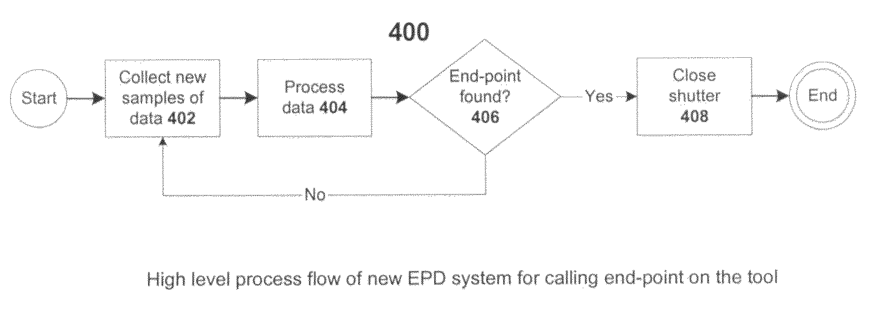
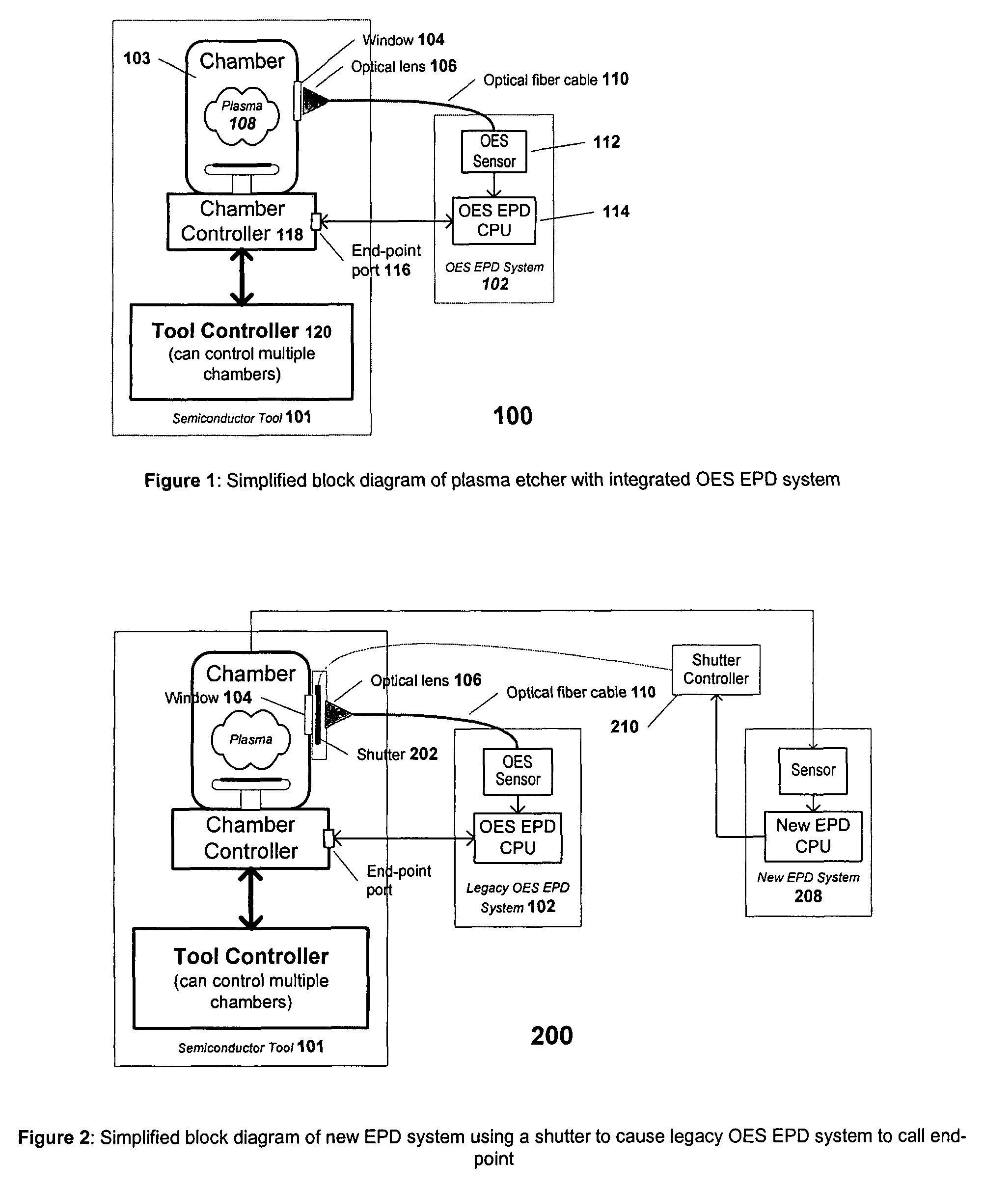
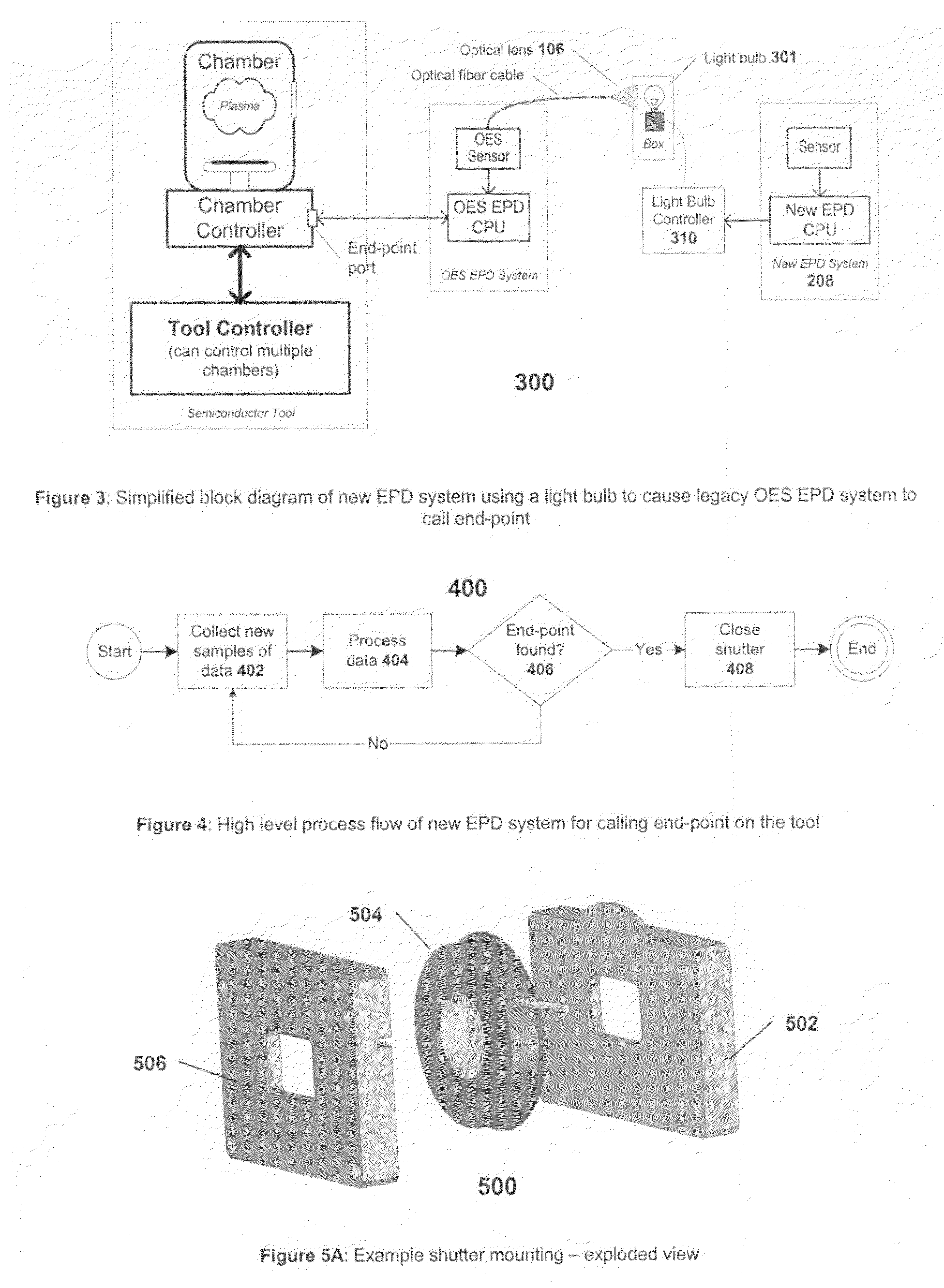
[0016]Embodiments in accordance with the present invention allow a second end-point determination (EPD) system to actively control the end-pointing of a semiconductor process chamber, by leveraging a legacy EPD system already integrated with the chamber. In one embodiment, the second EPD system controls a shutter that regulates the amount of light transmitted between a plasma light source and an optical emission spectroscopy (OES) sensor of the legacy OES EPD system. In this embodiment, the legacy OES EPD system is pre-configured to call end-point when an artificial end-point condition occurs, i.e. the intensity of light falls below a pre-set threshold. When the second EPD system determines that an actual end-point condition has been reached, it closes the shutter which causes the light intensity being read by the OES sensor to fall below the pre-set threshold. This in turn triggers an end-point command to the chamber from the legacy OES EPD system.

[0017]Many plasma-based semiconduc...


PUM

PropertyMeasurementUnit
intensity at wavelengthaaaaaaaaaa
voltageaaaaaaaaaa
voltageaaaaaaaaaa

Abstract

Embodiments in accordance with the present invention allow a second end-point determination (EPD) system to actively control the end-pointing of a semiconductor process chamber, by leveraging a legacy EPD system that is already integrated with the chamber. In one embodiment, the second EPD system controls a shutter that regulates the amount of light transmitted between a plasma light source and an optical emission spectroscopy (OES) sensor of the legacy OES EPD system. In this embodiment, the legacy OES EPD system is pre-configured to call end-point when an artificial end-point condition occurs, i.e. the intensity of light falls below a pre-set threshold. When the second EPD system determines an actual end-point condition has been reached, it closes the shutter which, causes the light intensity being read by the OES sensor to fall below the pre-set threshold. This in turn triggers an end-point command to the chamber from the legacy OES EPD system.

Description

BACKGROUND OF THE INVENTION[0001]Many semiconductor processing tools use an end-point determination (EPD) system to call active end-point on a process chamber. Major semiconductor processing tool vendors such as Applied Materials, Lam Research, and Tokyo Electron supply processing tools equipped with optical emission spectroscopy (OES)-based EPD systems already integrated with the chambers. Using these legacy EPD systems, a process engineer can configure the EPD systems to cause a recipe step to end when specific end-point criteria are met. One example of such specific criteria is when the intensity at wavelength 780 nm falls by 20% in a 5-second window. Such criteria are defined to capture signal features that represent the end-point of that particular processing step. Actively calling end-point is beneficial because it allows control of the processing time which can counteract variations in wafer processing. By contrast, without an EPD system the processing time is fixed, regardle...

Claims


Application Information

Patent Timeline
Patent Type & Authority Patents(United States)
IPC IPC(8): H04L12/28
CPCH01J37/32935H01J37/32963H01L22/26
Inventor CHUNG, SHERKLOZIC, TOMISLAVMONKOWSKI, JOSEPH RAYMONDWONG, GEOFFREY RODNEY
Owner PIVOTAL SYST CORP
Why Eureka
Try Eureka