Cyclonic separating apparatus

a technology of separating apparatus and cyclone, which is applied in the direction of cleaning equipment, domestic applications, applications, etc., can solve the problems of reducing the likelihood of larger particles of dirt and dust causing blockages downstream of the shroud, and achieve the effect of more efficient use of spa

Inactive Publication Date: 2011-01-25
DYSON TECH LTD
View PDF26 Cites 65 Cited by
  • Summary
  • Abstract
  • Description
  • Claims
  • Application Information

AI Technical Summary

Benefits of technology

[0010]It is an object of the present invention to provide cyclonic separating apparatus which is more compact than known arrangements. It is a further object of the invention to provide an arrangement of passageways within a cyclonic separating apparatus which allow more efficient use of space when compared to known arrangements.

Problems solved by technology

Further, the above arrangement reduces the likelihood of larger particles of dirt and dust causing blockages downstream of the shroud.

Method used


Image

  • Cyclonic separating apparatus
  • Cyclonic separating apparatus
  • Cyclonic separating apparatus

Examples


Embodiment Construction

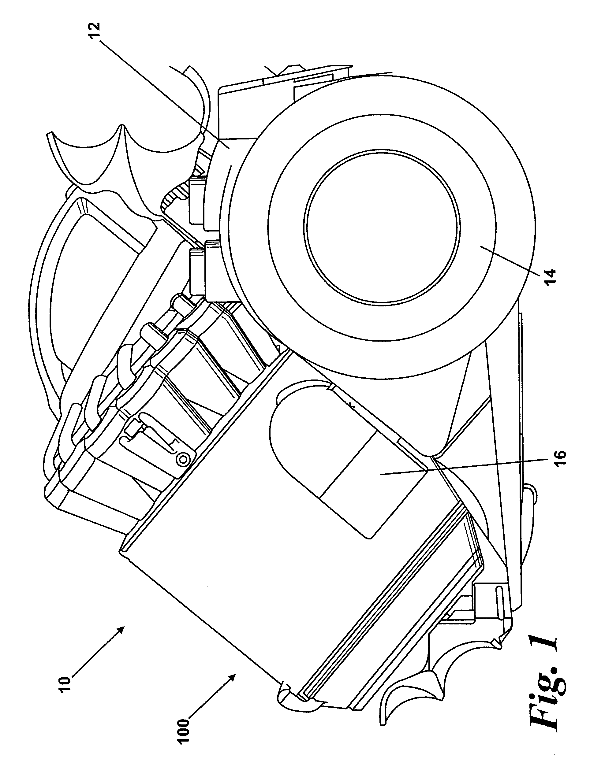
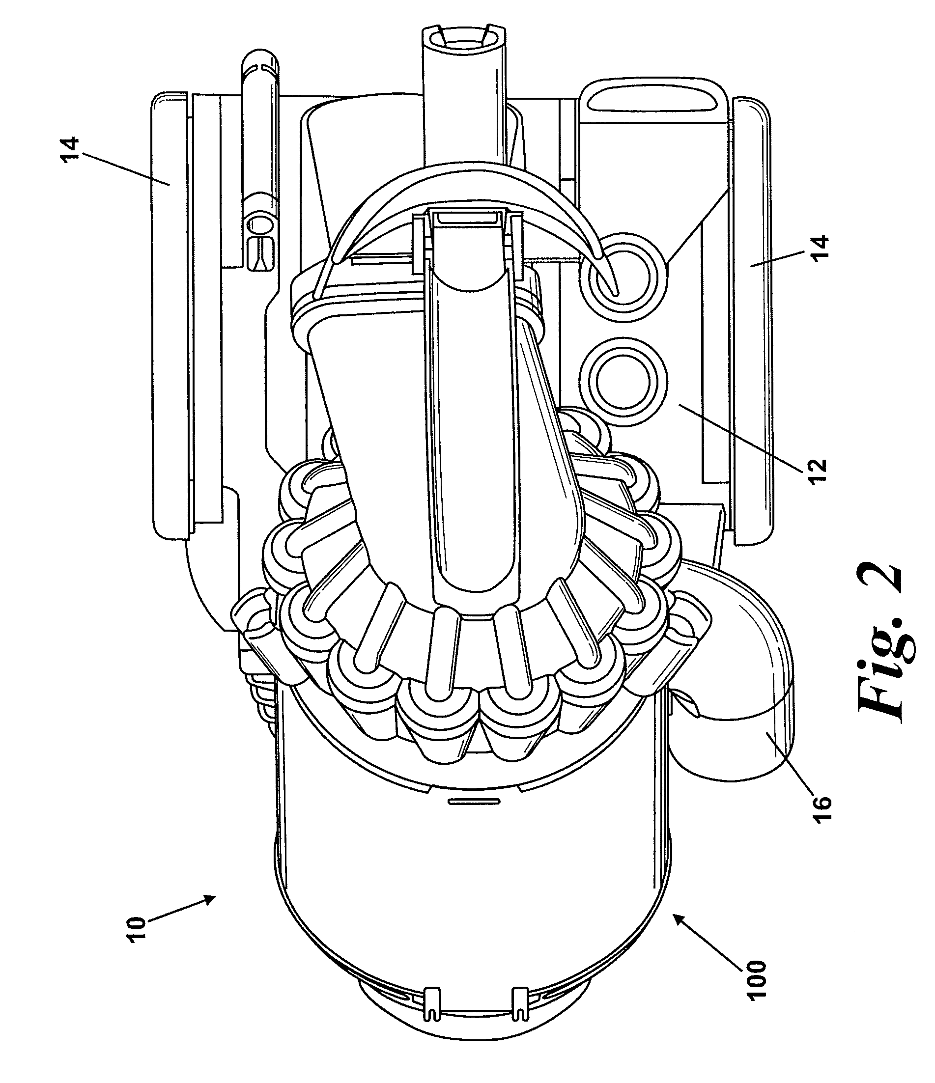
[0031]A cylinder vacuum cleaner 10 incorporating cyclonic separating apparatus according to the invention is shown in FIGS. 1 and 2. The vacuum cleaner 10 has a main body 12 housing a motor and fan unit (not shown) and to which a pair of wheels 14 is attached. The wheels 14 allow the main body 12 of the vacuum cleaner 10 to be maneuvered across a floor surface. A dirty air inlet 16 is formed on the main body 12. A hose and wand assembly (not shown) can be connected to the dirty air inlet 16 in order to enable a user to clean a floor surface.

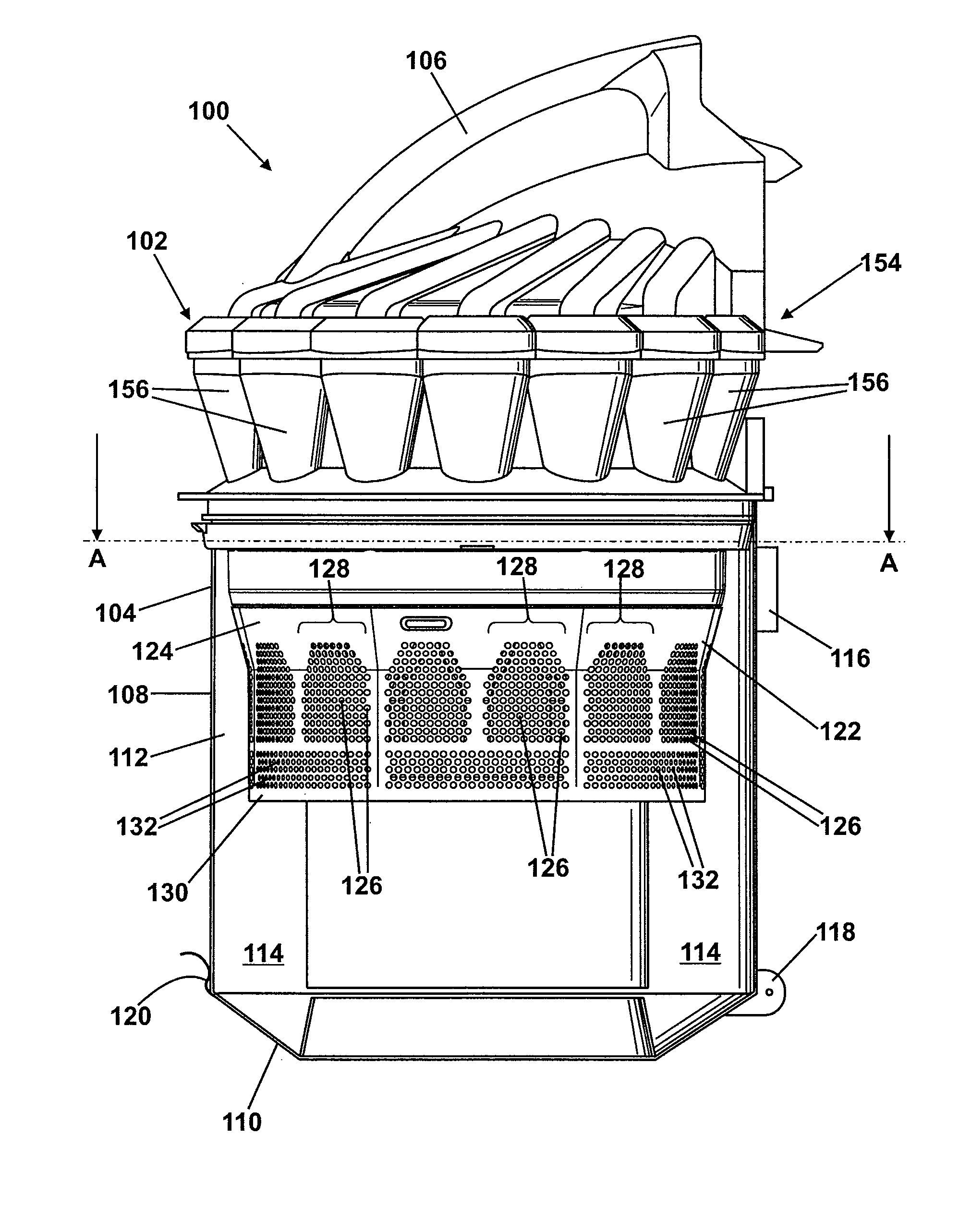
[0032]Cyclonic separating apparatus 100 according to the invention is releasably attached to the main body 12. The interior of the cyclonic separating apparatus 100 is in communication with the dirty air inlet 16 through which a dirt-laden airflow enters the cyclonic separating apparatus 100. The cyclonic separating apparatus 100 can be removed from the main body 12 for emptying purposes.

[0033]The cyclonic separating apparatus 100 is shown in mor...


PUM

PropertyMeasurementUnit
depthaaaaaaaaaa
inner circumferenceaaaaaaaaaa
collection areaaaaaaaaaaa

Abstract

A cyclonic separating apparatus includes a cyclonic separator for separating dirt and dust from an airflow, an inlet to the cyclonic separator and a shroud comprising a wall having a multiplicity of through-holes forming an outlet from the cyclonic separator. The apparatus also includes a plurality of separate passageways provided immediately downstream of the through-holes. By providing this arrangement, the separate passageways can be located around other parts of the cyclonic separating apparatus inwardly of the shroud, allowing for better packaging of the components of the cyclonic separating apparatus. The shroud may be reduced in size because some of the space previously required for a single, large passageway can be used for other components of the cyclonic separating apparatus such a collector or a cyclone. The reduction in size of the shroud in turn allows for the cyclonic separating apparatus to be more compact.

Description

REFERENCE TO RELATED APPLICATION[0001]This application claims the priority of United Kingdom Application No. 0721468.7, filed Nov. 1, 2007, the contents of which are incorporated herein by reference.FIELD OF THE INVENTION[0002]The present invention relates to cyclonic separating apparatus. Particularly, but not exclusively, the present invention relates to cyclonic separating apparatus for a vacuum cleaner.BACKGROUND OF THE INVENTION[0003]Vacuum cleaners which utilise cyclonic separators are well known. Examples of such vacuum cleaners are shown in EP 0 042 723, EP 1 370 173 and EP 1 268 076. In general, an airflow in which dirt and dust is entrained enters a first cyclonic separator via a tangential inlet which causes the airflow to follow a spiral or helical path within the first cyclonic separator so that the dirt and dust is separated from the airflow. Relatively clean air passes out of the first cyclonic separator while the separated dirt and dust is collected therein. In some ...

Claims


Application Information

Patent Timeline
Patent Type & Authority Patents(United States)
IPC IPC(8): A47L9/16
CPCA47L9/1616A47L9/1633A47L9/1641B04C5/10B04C5/13B04C5/26A47L9/1666A47L9/16A47L9/1608A47L9/1658A47L9/1683B04C5/08B04C5/185B04C5/187
Inventor FOLLOWS, THOMAS JAMES DUNNINGSTOKES, ANDREW PHILLIP
Owner DYSON TECH LTD
Why Eureka
Try Eureka