Connecting structure for steel frame columns and steel frame girders

a technology of connecting structure and steel frame girder, which is applied in the direction of buildings, constructions, towers, etc., can solve the problems of parts being broken, no sufficient yield strength, and no sufficient yield strength, and achieves sufficient yield strength, sufficient yield strength, and smooth transmission

Inactive Publication Date: 2011-01-25
ITEC CORP +1
View PDF24 Cites 37 Cited by
  • Summary
  • Abstract
  • Description
  • Claims
  • Application Information

AI Technical Summary

Benefits of technology

[0009]The connective structure for steel frame columns and steel frame girders according to the invention enables tensile, compressive and shearing forces working on the steel frame columns and the steel frame girders via connective fittings to be smoothly transmitted and sufficient yield strength against these forces to be thereby obtained. As a result, there is no need to build connective fittings and constituent members of high strength steel and / or designing them greater in thickness and diameter or to use plural reinforcing members to give the connective structure sufficient yield strength, and the costs and construction periods can be thereby reduced.

Problems solved by technology

However, the conventional connective fittings used in the connective structures described above involve a problem that they have no sufficient yield strength against tensile, compressive and shearing forces.
Especially, the web parts of split Ts and the bolt parts provided at one end each of paddle bolts are poor in yield strength against tensile and compressive forces working in the rectangular direction, involving a problem that these parts may be broken even before the tensile and compressive forces reach the web parts of steel frame columns.
There is another problem that, since the connective fittings are connected on the flange parts of steel frame columns, forces from the steel frame columns are always transmitted via the flange parts of the steel frame columns.
Thus, the flange parts of steel frame columns become even poorer in yield strength against the tensile and compressive forces working on them in the rectangular direction in the farther areas from the central position in their shorter side direction and, if excessively high tensile and compressive forces are transmitted to the flange parts of the steel frame columns via the connective fittings, not only the connective fittings but also the flange parts of the steel frame columns may be broken in this area.
These circumstances are leading to a trend of making the connective structure greater in yield strength by building connective fittings such as split Ts and paddle bolts, tightening items such as bolts and nuts, and constituent members of steel frame columns such as flange parts of high strength steel and / or designing them greater in thickness and diameter, but the loss of yield strength due to bolt inserting holes and the like has also to be made up for, resulting in the need to use plural reinforcing members including gusset plates and reinforcing steel plates.
As a consequence, the manufacturing cost of constituent members as well as the working cost and carriage cost resulting from the increased number of constituent members are rising, also entailing delays in construction schedules.

Method used


Image

  • Connecting structure for steel frame columns and steel frame girders
  • Connecting structure for steel frame columns and steel frame girders
  • Connecting structure for steel frame columns and steel frame girders

Examples


Embodiment Construction

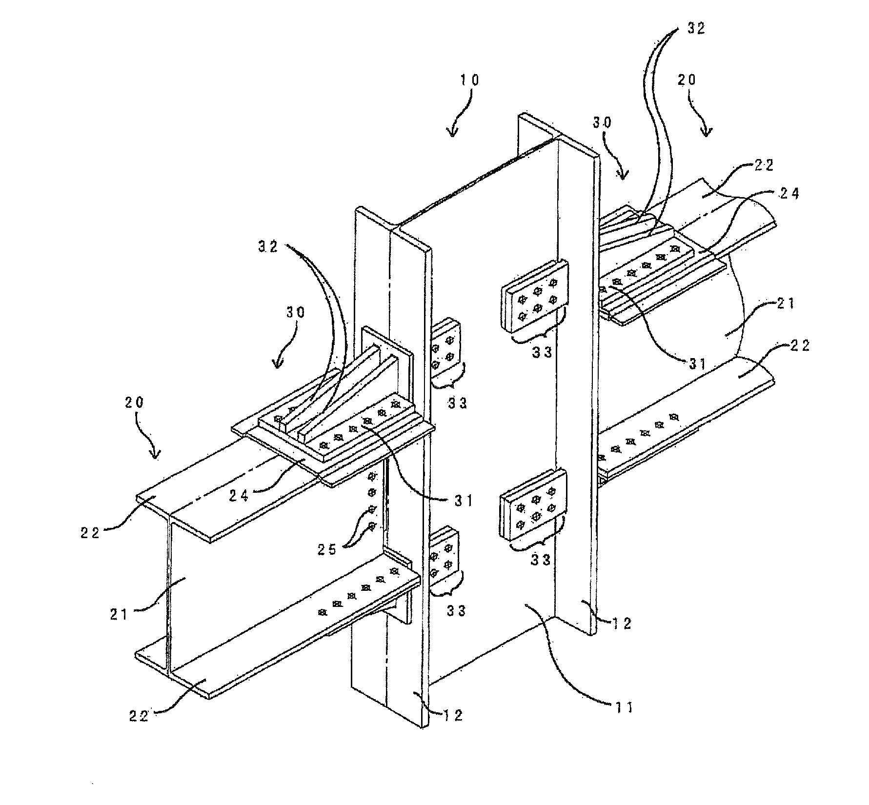
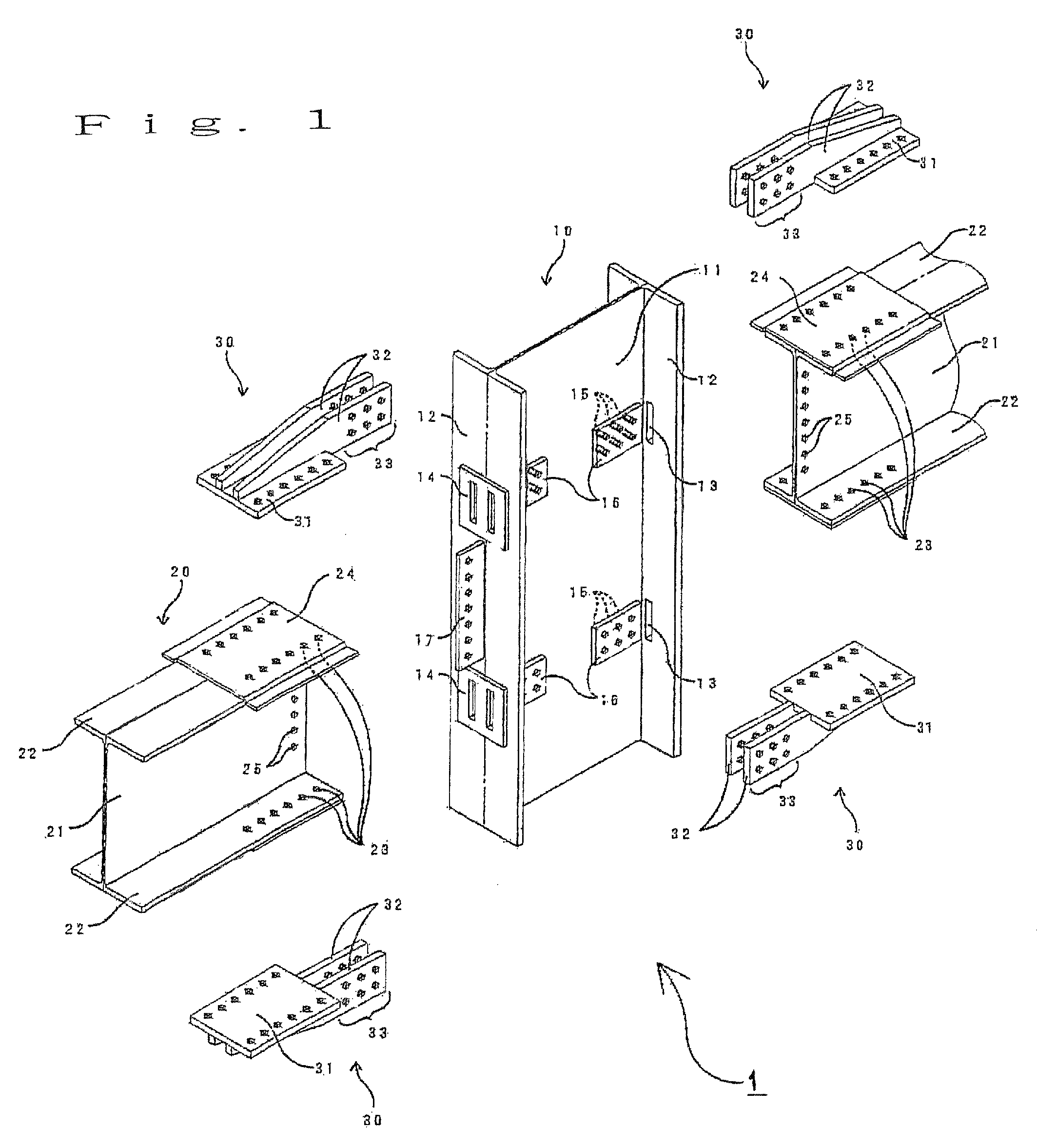
[0019]An exemplary embodiment of the present invention will be described below with reference to the accompanying drawings. FIG. 1 shows a perspective view of members constituting a connective structure of this exemplary embodiment. As shown in FIG. 1, a connective structure 1 is provided with an H beam-built steel frame column 10 and an H beam-built steel frame girder 20 crossing the steel frame column 10, and connects them with connective fittings 30. The steel frame column 10 has a web part 11 and flange parts 12 disposed on two sides of the web part 11. The steel frame girder 20 has a web part 21 and flange parts 22 disposed on two sides of the web part 21.

[0020]Two slit holes 13 are formed in each of the flange parts 12 of the steel frame column 10 symmetrically with respect to the center in the shorter side direction of the area where it crosses the flange parts 22 of the steel frame girder 20. In order to reinforce the yield strengths of the flange parts 12 against the boring...


PUM

PropertyMeasurementUnit
angleaaaaaaaaaa
areasaaaaaaaaaa
strengthaaaaaaaaaa

Abstract

Sufficient yield strength is achieved against tensile, compressive and shearing forces working on steel frame columns and steel frame girders by using simply configured connective fittings to reduce costs and construction periods. For this purpose, a connective structure of highly rigid steel frame columns and steel frame girders formed by connecting steel frame columns and steel frame girders each having a web part and flange parts with connective fittings is provided. Each of the connective fittings has a bottom plate part and, on a surface of the bottom plate part, side plate parts which rise at a substantially right angle to the bottom plate part and have inserting areas extending farther than a tip of the bottom plate part in the state of rising at the substantially right angle. On the other hand, slit holes are formed in the flange parts of the steel frame columns in the area where the flange parts cross the flange parts of the steel frame girders, the inserting areas of the side plate parts are inserted into the slit holes, the inserting areas of the side plate parts are fixed in a state of opposing the web parts of the steel frame columns, and the bottom plate parts of the connective fittings are fixed in a state of opposing the flange parts of the steel frame girders.

Description

BACKGROUND OF THE INVENTION[0001]1. Field of the Invention[0002]The present invention relates to a connective structure for steel frame columns and steel frame girders built of H beams.[0003]2. Description of the Related Art[0004]Known connective structures for H beam-built steel frame columns and steel frame girders include one which uses T-shaped fittings, so-called split Ts, as described in JP-A-07-102635 cited below. According to JP-A-07-102635, the flange parts of each connective fitting have plural bolt inserting holes, an inclined face is formed from the bolt inserting holes of the connective fittings in contact with steel frame columns toward their ends, and the flange parts are tension-connected to the steel frame columns by fastening with high strength bolts pressed through the bolt inserting holes in a state of being held in contact with the flange parts of the steel frame columns. On the other hand, the web part of each connective fitting has plural bolt inserting holes,...

Claims


Application Information

Patent Timeline
Patent Type & Authority Patents(United States)
IPC IPC(8): E04H12/00
CPCE04B1/2403E04B2001/2415E04B2001/2445E04B2001/2448E04B1/24E04B1/19E04B1/38
Inventor OHATA, EIICHIWAKASUGI, KAZUOHIROSAWA, KOICHINARITA, KENJI
Owner ITEC CORP
Why Eureka
Try Eureka