Wind turbine tower, a wind turbine, a wind turbine tower elevator and a method for assembling a wind turbine tower

a technology of wind turbines and elevators, which is applied in the direction of machines/engines, manufacturing tools, and final product manufacture, etc., can solve the problems of high specialised and expensive rolling equipment, welding reduces the fatigue limit of the tower, and the strength of the tower is affected

Active Publication Date: 2011-02-01
VESTAS WIND SYST AS
View PDF19 Cites 30 Cited by
  • Summary
  • Abstract
  • Description
  • Claims
  • Application Information

AI Technical Summary

Benefits of technology

[0011]It is advantageous to make the tower rings of a wind turbine overlap, in that it provides for a simple tower design which can be manufactured be means of low-tech manufacturing means.
[0078]Assembling the tower at or in close proximity of the site where the tower is to be erected is advantageous, in that transport over long distances, of large tower parts which are difficult to manage, is avoided. Furthermore, assembling the tower at or in close proximity of the erection site is possible due to the fact, that a bolted load carrying joint can be made correctly even under relatively primitive conditions, whereas a welded load carrying joint demands a more controlled environment to be made reliably.

Problems solved by technology

The manufacturing facilities for large modern wind turbine towers demands a building with a free height of 8 m, access to lifting equipment with a capacity of 70 t and highly specialised and expensive rolling equipment.
Furthermore, welding reduces the towers fatigue limit and thereby its strength, which makes it necessary to make the tower or at least parts of the tower of plates thicker than what otherwise, would be necessary.
But the metal parts have a complex design and are thereby difficult and expensive to manufacture.

Method used


Image

  • Wind turbine tower, a wind turbine, a wind turbine tower elevator and a method for assembling a wind turbine tower
  • Wind turbine tower, a wind turbine, a wind turbine tower elevator and a method for assembling a wind turbine tower
  • Wind turbine tower, a wind turbine, a wind turbine tower elevator and a method for assembling a wind turbine tower

Examples


Embodiment Construction

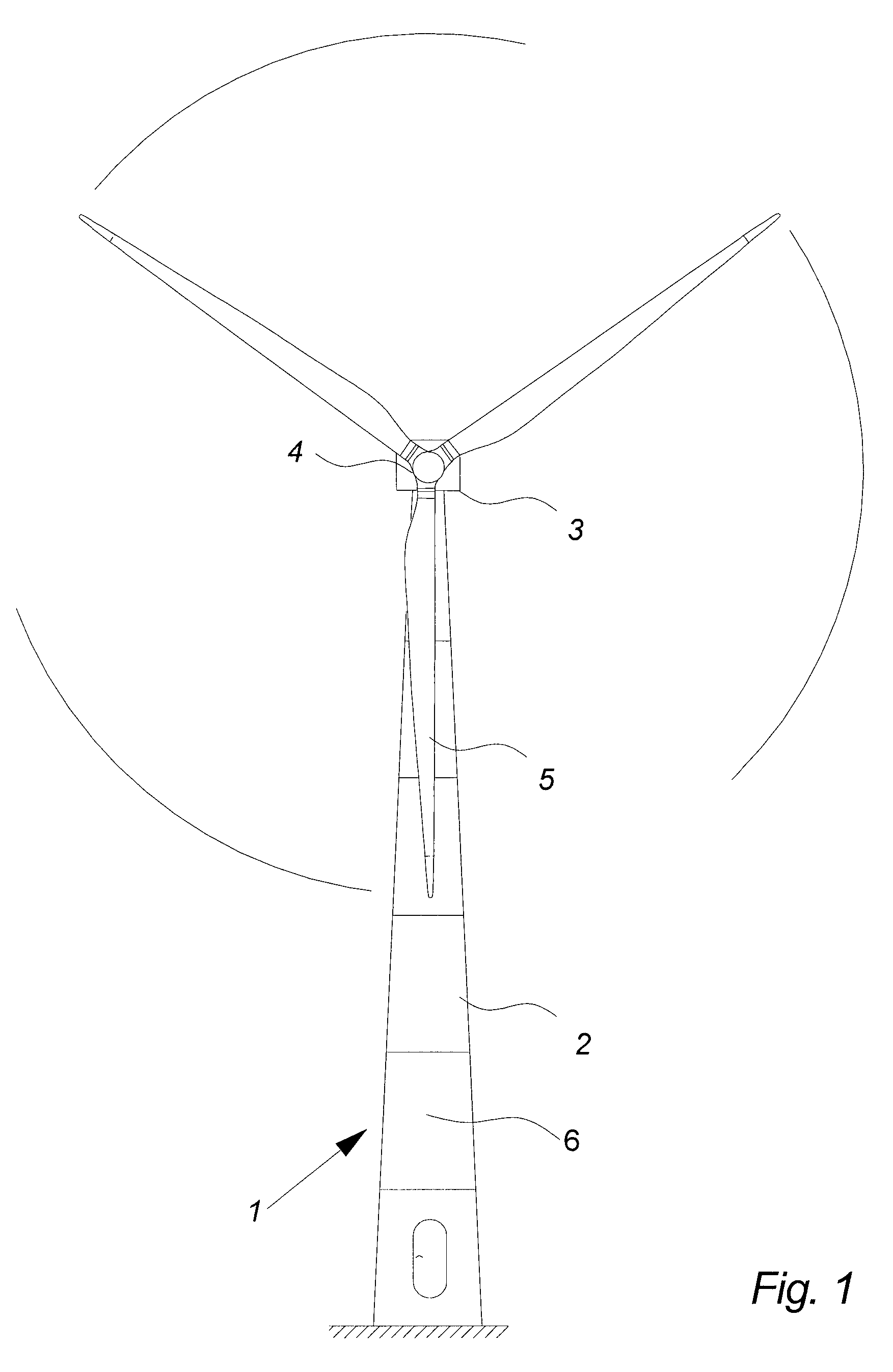
[0093]FIG. 1 illustrates a wind turbine 1 known in the art, comprising a tapered tower 2, which is subdivided into a number of tower sections 6. A wind turbine nacelle 3 is positioned on top of the tower 2.

[0094]The wind turbine rotor 4, comprising a number of wind turbine blades 5, is connected to the nacelle 3 through the low speed shaft which extends out of the nacelle 3 front.

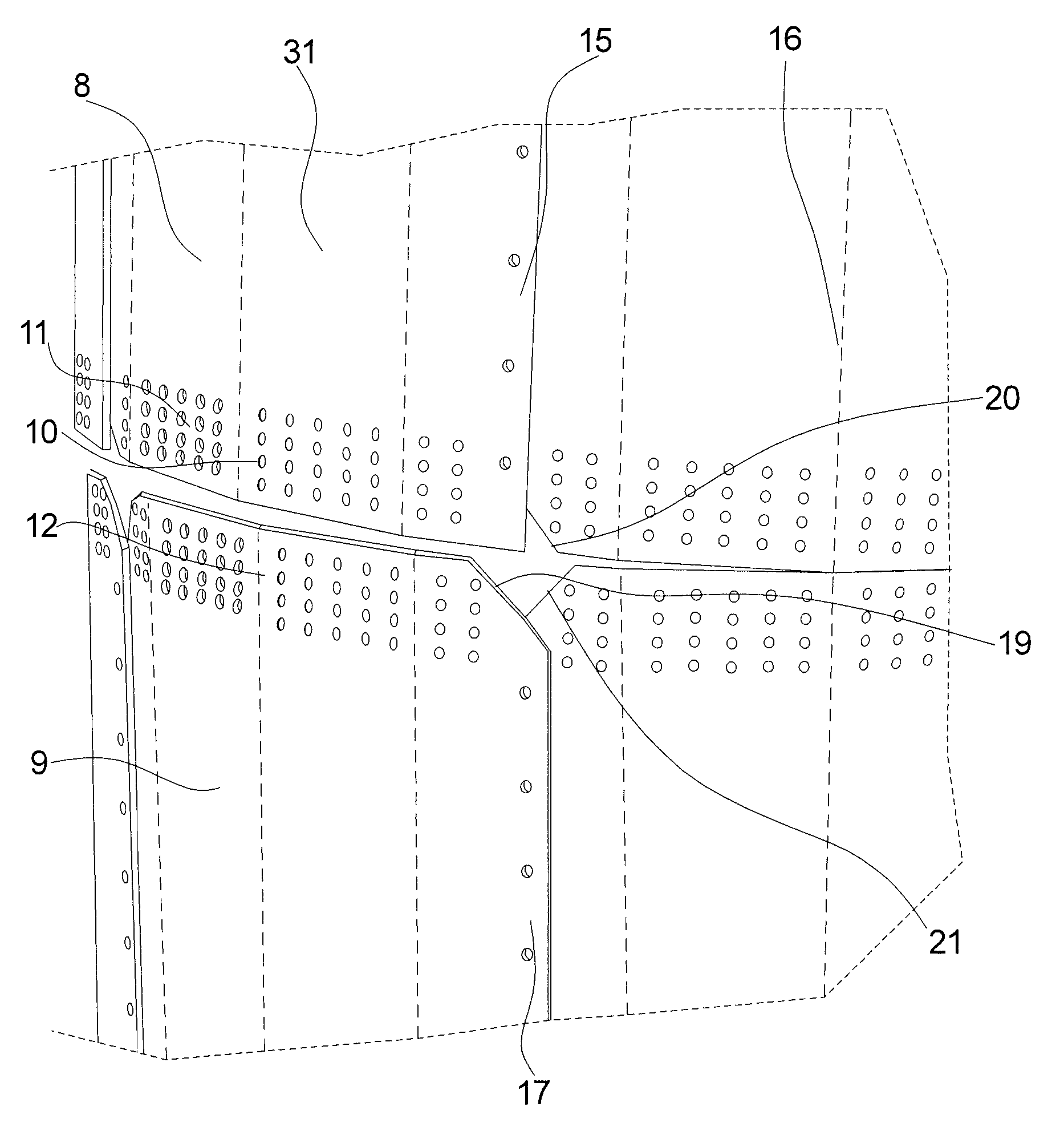
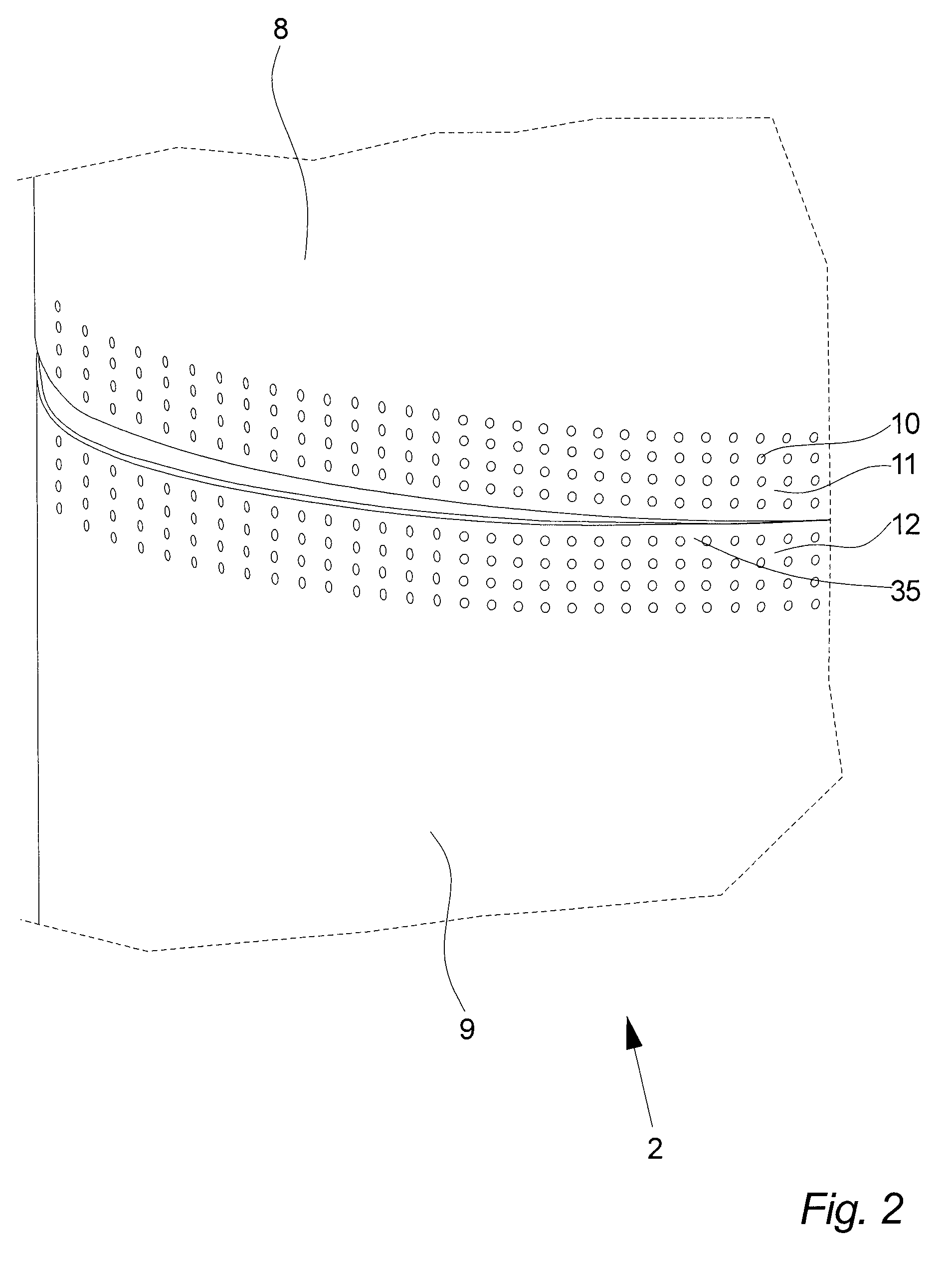
[0095]FIG. 2 illustrates a section of a wind turbine tower 2 according to the invention immediately before the assembly of two round tower rings 14, as seen in perspective. FIG. 2 shows an upper tower ring 8 on its way to be placed on a lower tower ring 9 making the bottom section 11 of the upper ring 8 overlap the top section 12 of the lower ring 9 in a horizontal overlap region 35. When the tower rings 8, 9 are in place the two rings are joined by bolting or riveting the rings 8, 9 together through the rows of bolt holes 10.

[0096]In this embodiment of the invention the tower rings 8, 9 are made as full 36...


PUM

PropertyMeasurementUnit
heightaaaaaaaaaa
diameteraaaaaaaaaa
bending angleaaaaaaaaaa

Abstract

The invention relates to a wind turbine tower comprising at least two annular tower rings placed vertically on top of each other. The wind turbine tower is characterized in that, a first tower ring overlaps at least a further tower ring of the at least two tower rings. The invention further relates to a wind turbine, a wind turbine tower elevator for use in a wind turbine tower and a method for assembling a wind turbine tower.

Description

CROSS-REFERENCE TO RELATED APPLICATIONS[0001]The present application is a continuation of pending International patent application PCT / DK2006 / 000027, filed Jan. 17, 2006, which designates the United States, the content of which is incorporated herein by reference.FIELD OF THE INVENTION[0002]The invention relates to a wind turbine tower comprising at least two annular tower rings placed vertically on top of each other, a wind turbine, a wind turbine tower elevator for use in a wind turbine tower and a method for assembling a wind turbine tower.BACKGROUND OF THE INVENTION[0003]A wind turbine known in the art comprises a tapered wind turbine tower and a wind turbine nacelle positioned on top of the tower. A wind turbine rotor with three wind turbine blades is connected to the nacelle through a low speed shaft, which extends out of the nacelle front as illustrated on FIG. 1.[0004]Wind turbine towers typically comprise a number of tapered round tower sections mounted on top of each other...

Claims


Application Information

Patent Timeline
Patent Type & Authority Patents(United States)
IPC IPC(8): E04H12/00
CPCE04H12/08E04H12/34F03D1/001F03D11/00B66B9/187F03D11/04Y10T29/49963F05B2230/50F05B2250/131Y02E10/728F03D80/00F03D13/20F03D13/10F03D80/50Y02E10/72Y02P70/50
Inventor OLLGAARD, BORGE
Owner VESTAS WIND SYST AS
Why Eureka
Try Eureka