Dual clutch transmission

a clutch transmission and clutch technology, applied in the direction of transmission elements, belts/chains/gearings, toothed gearings, etc., can solve the problems of increasing the rotational speed in the area of the countershaft, the relative high torque load of the countershaft, and the difficulty in rigid support of the constant output gear set, etc., to achieve the effect of small overall space and more difficult attachmen

Inactive Publication Date: 2011-02-01
GETRAG GETRIEBE & ZAHNRADFABRIK HERMANN HAGENMEYER GMBH & CO KG
View PDF17 Cites 8 Cited by
  • Summary
  • Abstract
  • Description
  • Claims
  • Application Information

AI Technical Summary

Benefits of technology

[0018]This measure means firstly that the vehicle can be rocked out of situations purely through clutch control of the dual clutch. Secondly, driving the gear set for the reverse gear via an auxiliary shaft means that the transmission ratios for the first forward gear and the reverse gear can be matched to one another.
[0032]The arrangement of the highest and third-highest gear sets between the two bearings of the output shaft furthermore makes it comparatively easy in design terms to transpose the gear seats, in order thereby to obtain an optimum transmission synchronization to suit the particular application.

Problems solved by technology

This leads to a relatively high torque load on the countershaft.
Compared to constant drive solutions, however, there is an increase in the rotational speed in the area of the countershaft.
One problem with step-variable transmissions having constant output gear sets is that it is comparatively difficult to support the constant output gear set rigidly, so that it still has an acceptable tooth bearing contact area despite its comparatively large width.
This immediately negates the design advantage of the overall length achievable with this type of transmission.
A disadvantage to this is that there is a relatively large difference in the transmission ratios for the first forward gear and the reverse gear.

Method used


Image

  • Dual clutch transmission
  • Dual clutch transmission

Examples


Embodiment Construction

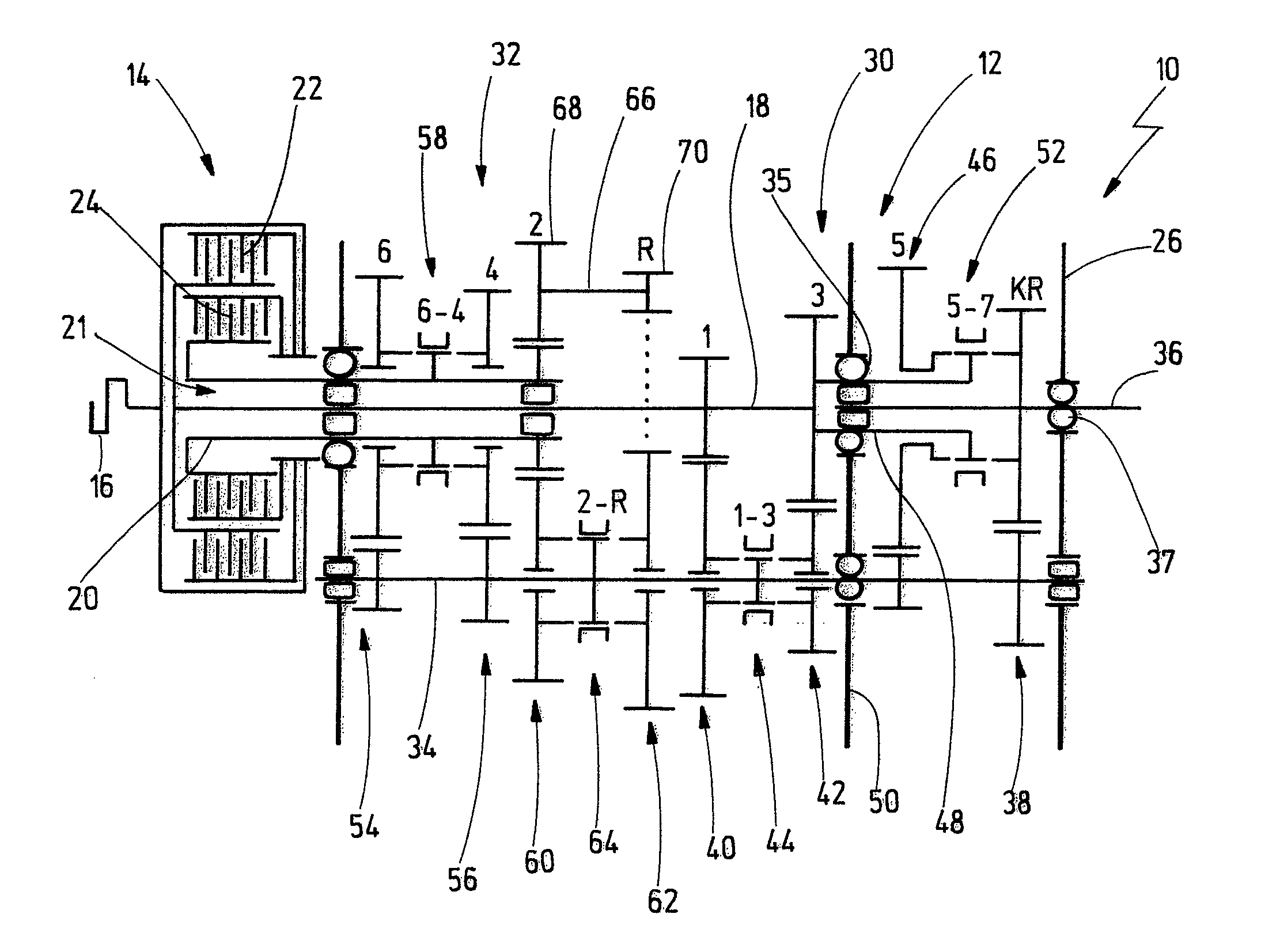
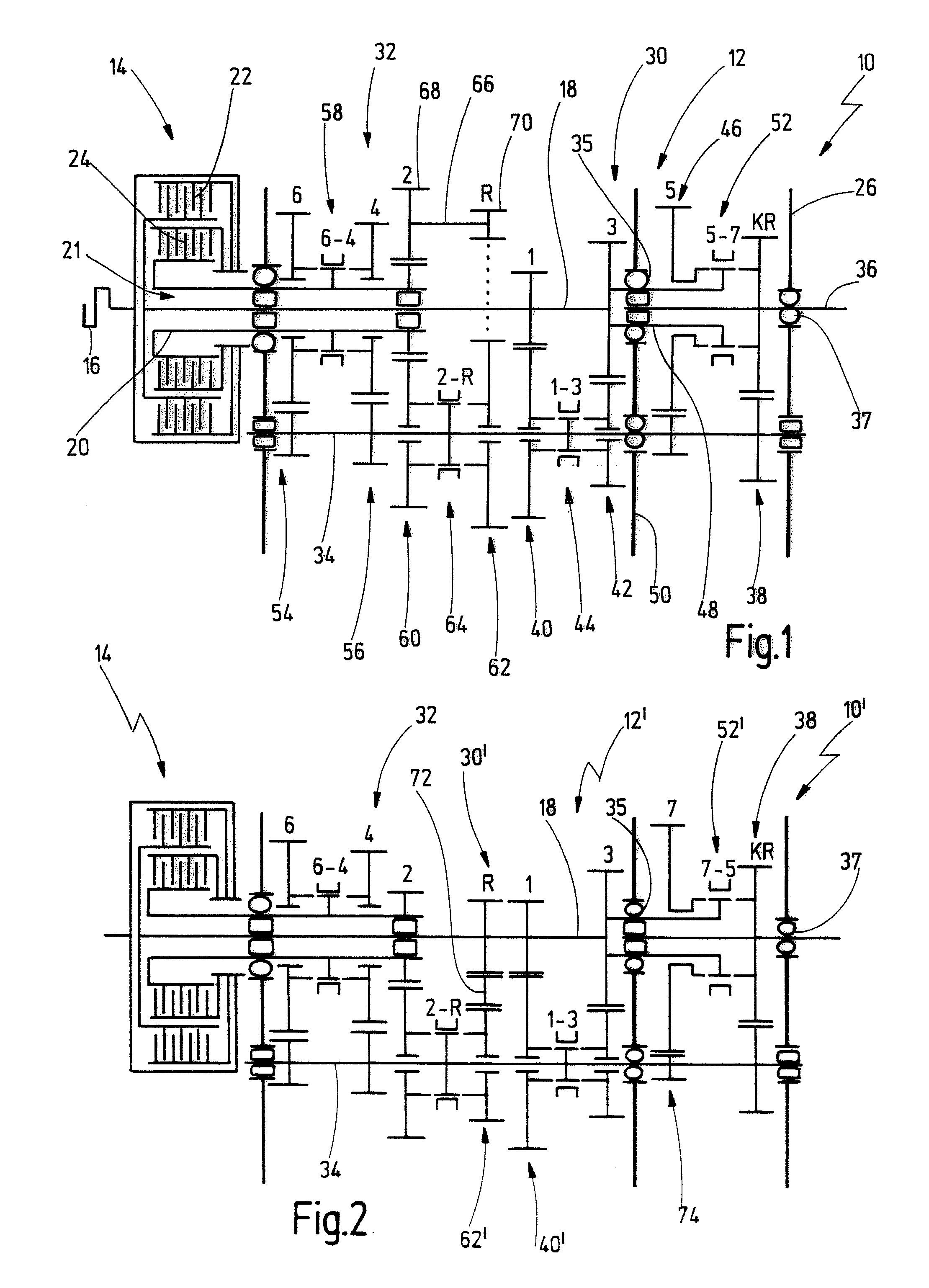
[0041]In FIG. 1 a dual clutch transmission according to the first aspect of the present invention is generally denoted by 10.

[0042]The dual clutch transmission 10 comprises a step-variable transmission 12 of spur gear type and a dual clutch arrangement 14. An input member of the dual clutch arrangement 14 is connected to a schematically indicated drive engine, such as an internal combustion engine 16.

[0043]The step-variable transmission 12 comprises a drive shaft arrangement 21 with a first drive shaft 18 and a second drive shaft 20 in the form of a hollow shaft supported coaxially with the former.

[0044]The dual clutch arrangement 14 comprises a first clutch 22, the output member of which is connected to the first drive shaft 18. The dual clutch arrangement 14 further comprises a second clutch 24, the output member of which is connected to the second drive shaft 20. The clutches 22, 24 may be nested one radially inside the other, as shown, or lie axially in series. The clutches 22, ...


PUM


Abstract

A dual clutch transmission has a housing, a drive shaft arrangement, an output shaft and a countershaft. A plurality of gear sets is supported on the drive shaft arrangement and the countershaft, respectively. The gear sets are shifted by means of respective shifting clutches in order to engage different gears. The countershaft is connected to the output shaft via a constant output gear set. The gear sets are divided between two gear trains. A first forward gear and a reverse gear are each assigned to a different gear train. The gear set for the reverse gear is driven via an auxiliary shaft, which is in turn driven via a specific gear set. The specific gear set is assigned to the same gear train as the reverse gear.

Description

CROSS-REFERENCE TO RELATED APPLICATIONS[0001]This application claims the priority of German patent application 10 2006 061.515 filed Dec. 18, 2006.BACKGROUND OF THE INVENTION[0002]The present invention relates to a dual clutch transmission, particularly for motor vehicles, having a housing, a drive shaft arrangement, an output shaft and a countershaft, a plurality of gear sets being supported on the drive shaft arrangement and / or the countershaft, the gear sets being shifted by means of respective shifting clutches in order to engage different gears, the countershaft being connected to the output shaft via a constant output gear set, and the gear sets being divided between two gear trains.[0003]Such a step-variable transmission is disclosed by DE 10 2005 005 338 B3. This known transmission is a so-called in-line transmission, that is to say a transmission intended for longitudinal installation in the motor vehicle.[0004]Such conventional in-line transmissions generally have a consta...

Claims


Application Information

Patent Timeline
Patent Type & Authority Patents(United States)
IPC IPC(8): F16H3/08
CPCF16H3/006F16H3/0915F16H2003/0822Y10T74/19228Y10T74/19288Y10T74/19242F16H2200/0056
Inventor NICKLASS, OLIVERMUELLER, ANDREAS
Owner GETRAG GETRIEBE & ZAHNRADFABRIK HERMANN HAGENMEYER GMBH & CO KG
Why Eureka
Try Eureka