Expandable lordosis stabilizing cage

a stabilizing cage and expandable technology, applied in the field of expandable stabilizing cages, to achieve the effect of increasing distance and reducing diameter

Inactive Publication Date: 2011-02-01
SIMMONS JR JAMES W
View PDF12 Cites 256 Cited by
  • Summary
  • Abstract
  • Description
  • Claims
  • Application Information

AI Technical Summary

Problems solved by technology

While still keeping with the critical requirement for substantially planar upper and lower surfaces, however, the surfaces may nonetheless be desirably provided surface irregularities for facilitating stable engagement of the elongate blocks with adjacent vertebral bodies.

Method used


Image

  • Expandable lordosis stabilizing cage
  • Expandable lordosis stabilizing cage
  • Expandable lordosis stabilizing cage

Examples


Embodiment Construction

[0046]Although those of ordinary skill in the art will readily recognize many alternative embodiments, especially in light of the illustrations provided herein, this detailed description is exemplary of the preferred embodiment of the present invention, the scope of which is limited only by the claims appended hereto.

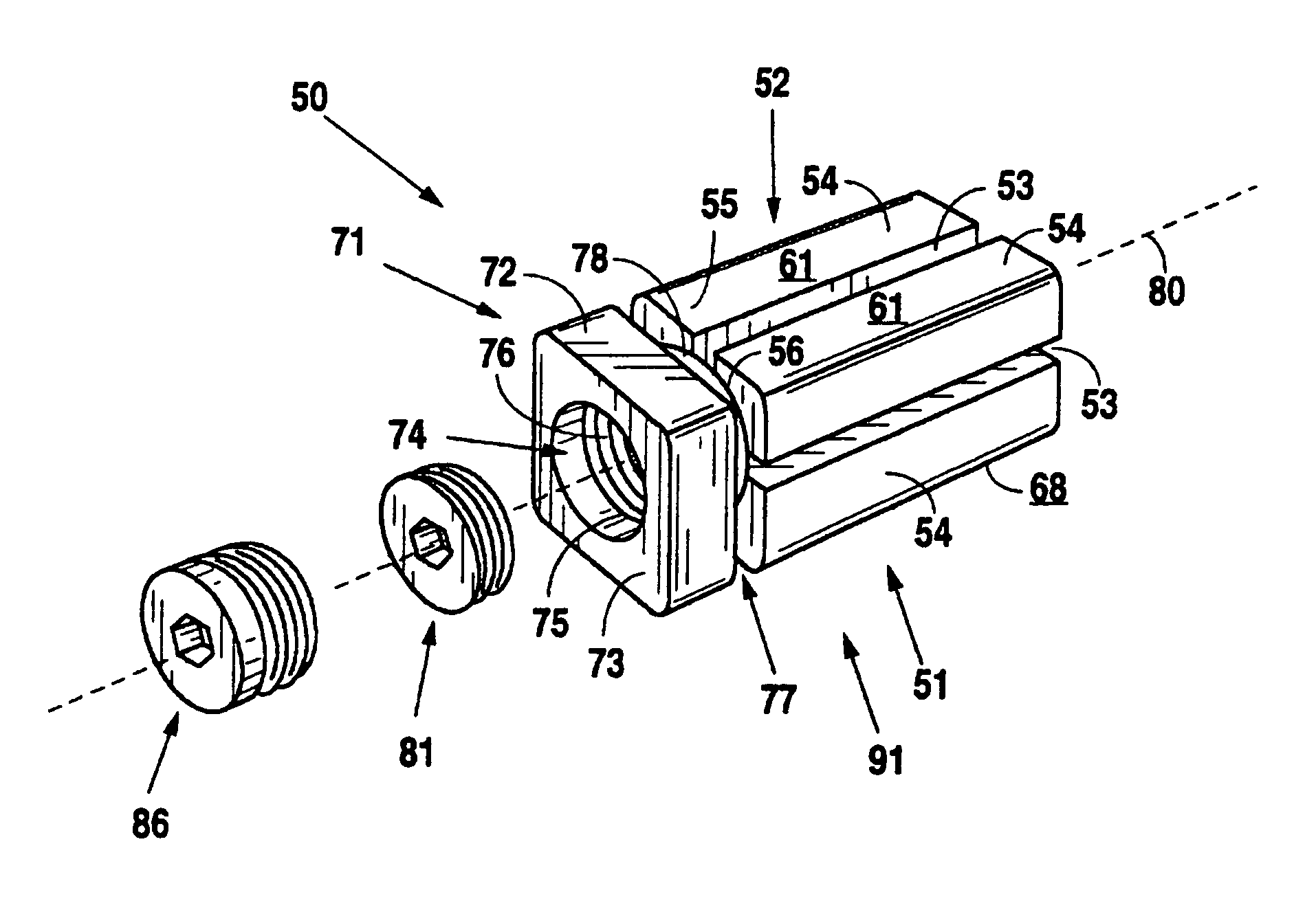
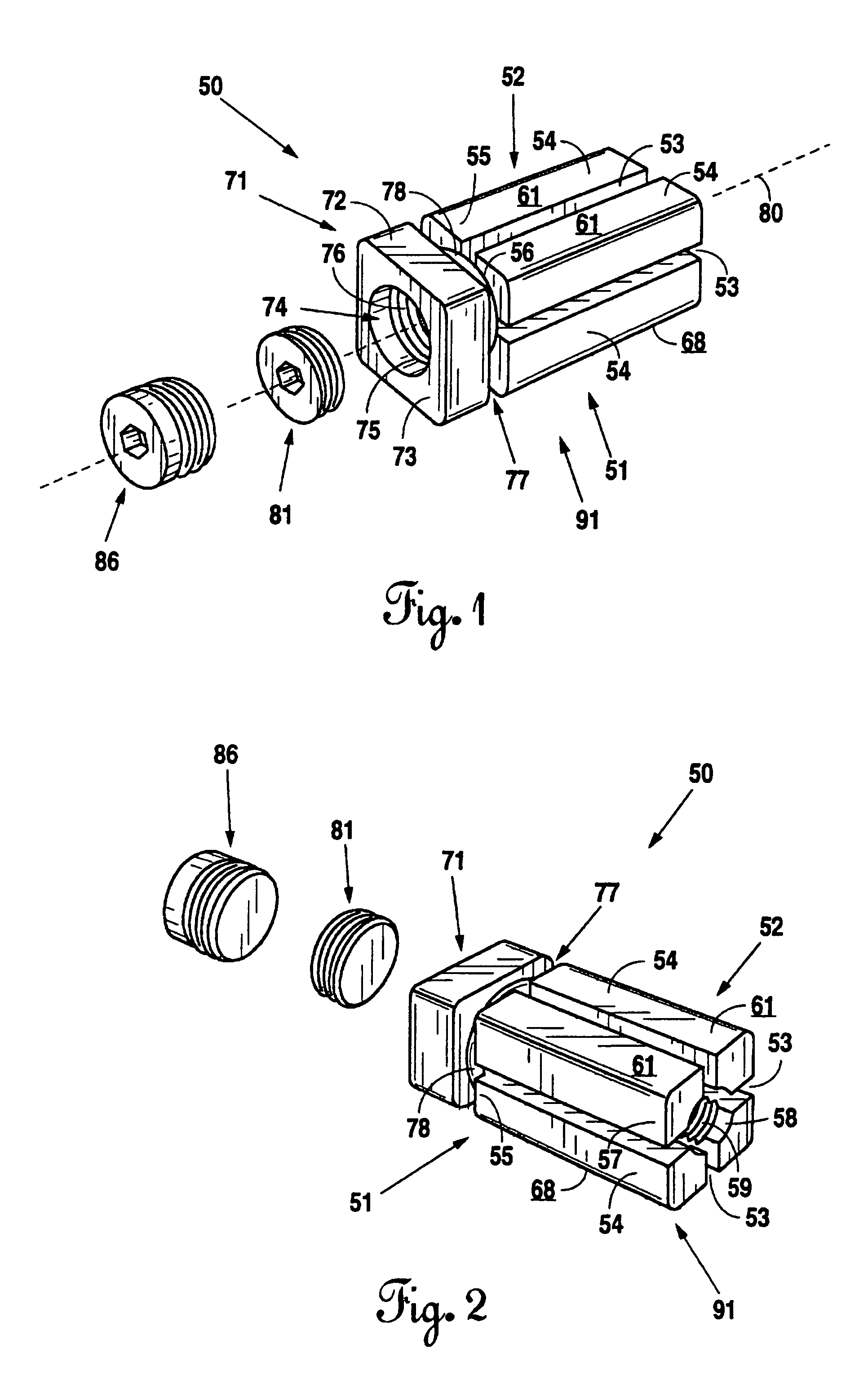
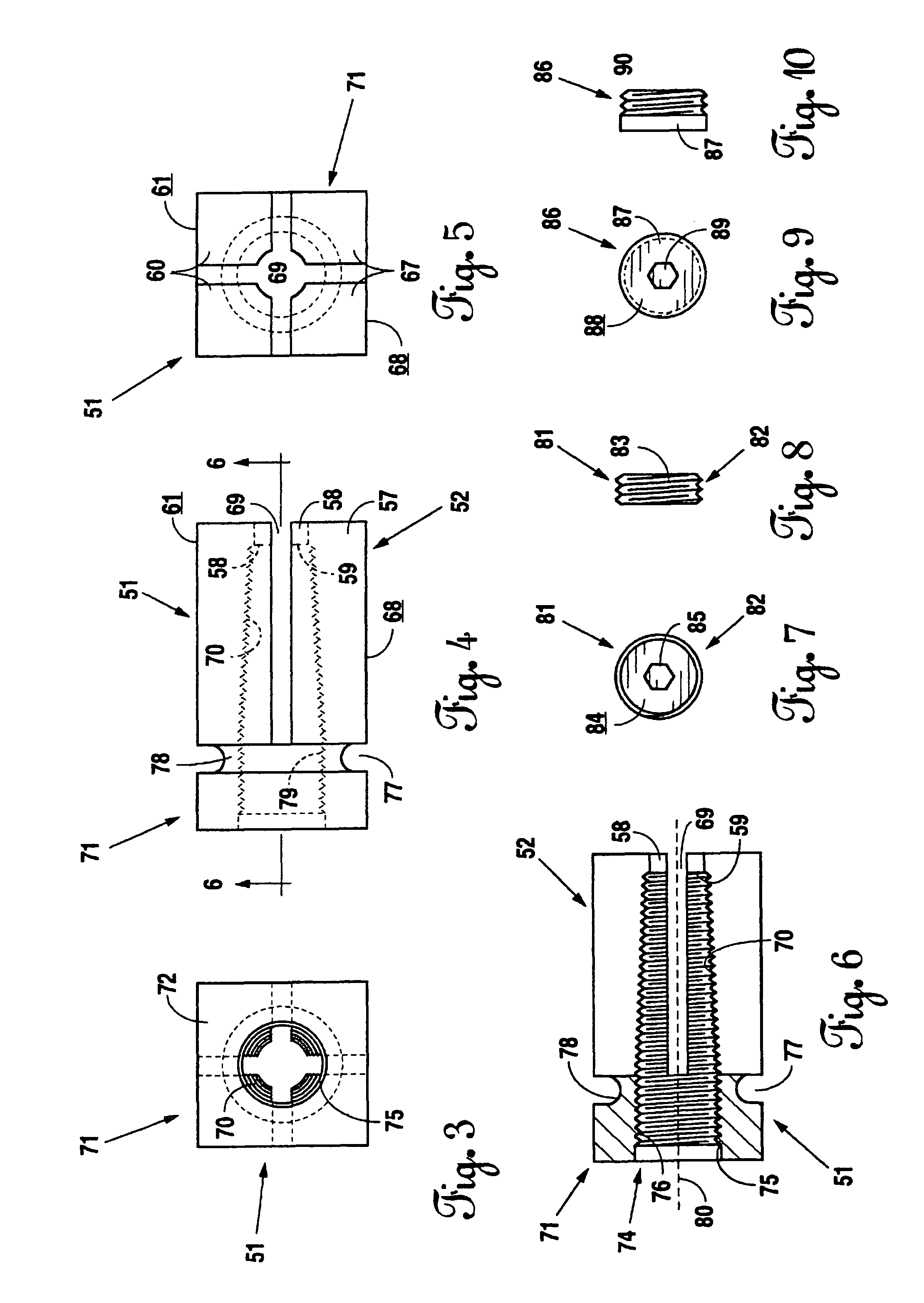
[0047]Referring now to the figures, and to FIGS. 1 and 2 in particular, the lordosis stabilizing cage 50 of the present invention is shown to generally comprise a body 51 and an expansion wafer 81. As shown the figures, the body 51 comprises a generally rectilinear expandable cage section 52 and a fixed cage section 71 arranged adjacent one to the other along a central axis 80 running longitudinally through the body 51. As shown in FIGS. 1 through 6, the expandable cage section 52 comprises a plurality of elongate blocks 54 extending from their proximal ends 55 from the fixed cage section 71. As shown in the figures, the elongate blocks 54 are generally defined by the p...


PUM


Abstract

An expandable stabilizing cage includes a body having a fixed cage section, an expandable cage section, formed as a number of elongate blocks, and a relief between the fixed and expandable cage sections. An orifice, which through the expandable cage section decreases in diameter with increased distance along the central axis of the body away from the fixed cage section, is provided through the body. The expandable stabilizing cage also includes a wafer, which, when inserted into the orifice through the body, causes outward flaring of the elongate bars for fixing the expandable stabilizing cage securely in place in the intervertebral disc space between two adjacent vertebral bodies. Upper elongate blocks have substantially planar upper surfaces. Lower elongate blocks have substantially planar lower surfaces. The surfaces may be provided with surface irregularities for facilitating stable engagement with adjacent vertebral bodies, exemplary irregularities including denticles, dimples, scores, grooves or small protuberances.

Description

RELATED APPLICATION[0001]This present application claims all available benefit, under 35 U.S.C. §119(e), to U.S. provisional patent application Ser. No. 60 / 728,228 filed Oct. 19, 2005. By this reference, the full disclosure, including the drawings, of U.S. provisional patent application Ser. No. 60 / 728,228 is incorporated herein as though now set forth in its entirety.FIELD OF THE INVENTION[0002]The present invention relates to medical devices. More particularly, the invention relates to an expandable stabilizing cage for replacement of a patient's intervertebral disc and fusion therethrough of the immediately superior and immediately inferior vertebral bodies, the expandable stabilizing cage being particularly adapted for either anterior or posterior insertion into the intervertebral space and for enhanced post-insertion stability.BACKGROUND OF THE INVENTION[0003]Patients suffering injury or deterioration of an intervertebral disc often require surgical intervention, which in some ...

Claims


Application Information

Patent Timeline
Patent Type & Authority Patents(United States)
IPC IPC(8): A61F2/44
CPCA61F2/4465A61F2/30723A61F2/30744A61F2/30965A61F2002/30438A61F2002/30538A61F2002/30556A61F2002/30579A61F2002/30594A61F2002/30598A61F2002/30736A61F2002/30774A61F2002/30831A61F2002/30841A61F2002/448A61F2220/0041A61F2250/0006A61F2250/0009A61F2310/00023A61F2002/30433
Inventor SIMMONS, JR., JAMES W.
Owner SIMMONS JR JAMES W
Why Eureka
Try Eureka