Optical time domain reflectometer

a reflectometer and optical time domain technology, applied in the field of optical time domain reflectometers, can solve the problems of optical communication system communication failure and poor working efficiency

Active Publication Date: 2011-02-01
YOKOGAWA ELECTRIC CORP
View PDF2 Cites 52 Cited by
  • Summary
  • Abstract
  • Description
  • Claims
  • Application Information

AI Technical Summary

Problems solved by technology

That is, the visible light emitted to the measured optical fiber from the visible light source of the OTDR leaks from a fault point and thus the user can easily find the fault point by visibly inspecting the leakage light.
However, to switch the mode between the OTDR function and the visible light source function, it is always necessary to switch connection of the measured optical fiber F1 (the incidence-emission port P1 or the emission port P2) and there is a problem of worsening the working efficiency.
Thus, there is a problem of a fear of occurrence of a serious accident causing a communication failure to occur in the optical communication system as visible light is emitted to the measured optical fiber F1 although the communication light is transmitted.

Method used


Image

  • Optical time domain reflectometer
  • Optical time domain reflectometer
  • Optical time domain reflectometer

Examples


Embodiment Construction

[0047]Referring now to the accompanying drawings, there is shown an embodiment of the invention.

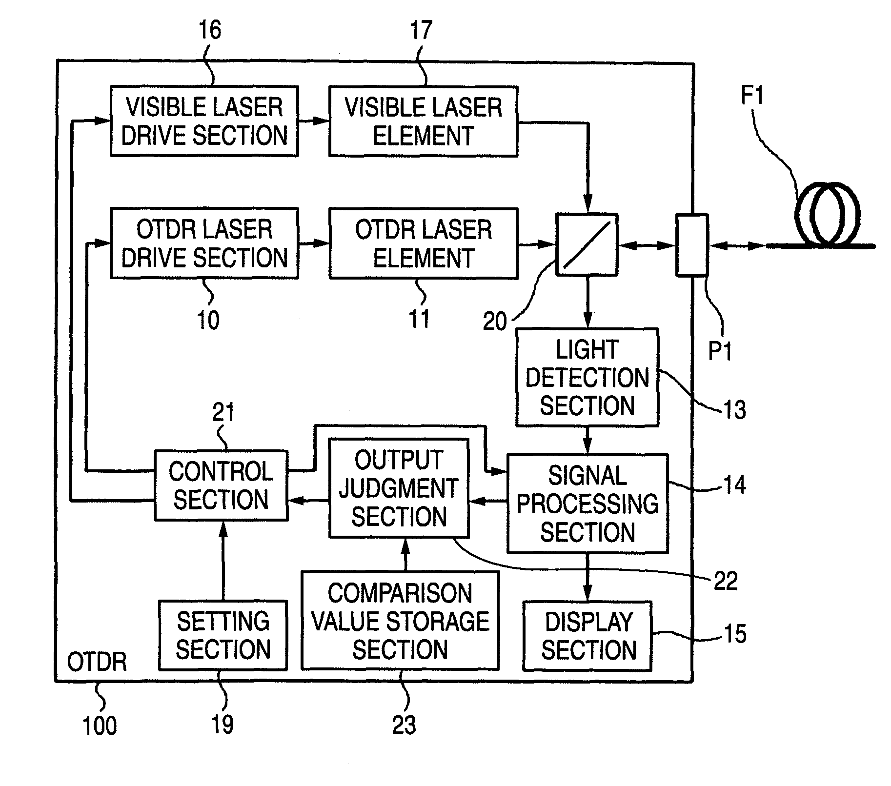
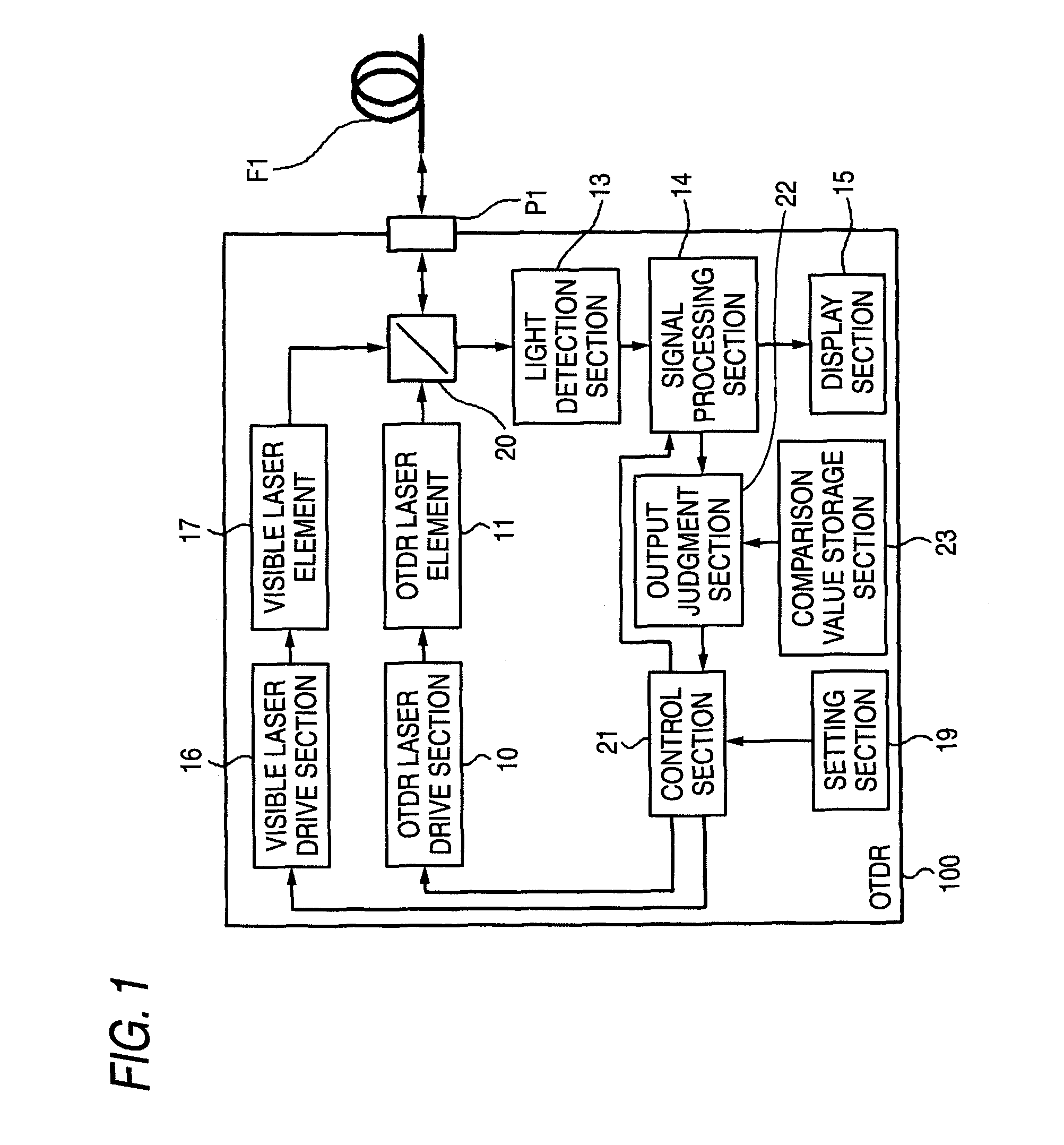
[0048]FIG. 1 is a block diagram to show one embodiment of the invention. Components identical with those previously described with reference to FIG. 4 are denoted by the same reference numerals in FIG. 1 and will not be discussed again. In FIG. 1, an optical directional coupler 20 is provided in place of the optical directional coupler 12 and a control section 21 is provided in place of the control section 18. An output judgment section 22 and a comparison value storage section 23 are newly provided and the emission port P2 is removed.

[0049]The optical directional coupler 20 emits OTDR measurement light from an OTDR laser element 11 and visible light from a visible laser element 17 through an incidence-emission port P1 to a measured optical fiber F1. The optical directional coupler 20 also emits light incident from the measured optical fiber F1 through the incidence-emission port P1 (retu...


PUM

PropertyMeasurementUnit
wavelengthaaaaaaaaaa

Abstract

An improvement is added to an optical time domain reflectometer for emitting pulsed light of invisible light to a measured optical fiber, receiving return light of the pulsed light by a light detection section, measuring the measured optical fiber, and emitting visible light for visible inspection of a fault point of the measured optical fiber to the measured optical fiber. The optical time domain reflectometer includes an incidence-emission port for emitting the invisible light and the visible light to the measured optical fiber and an output judgment section for judging that a communication light exists in the measured optical fiber based on the light power of the light detection section receiving light incident through the incidence-emission port in a state in which the pulsed light of the invisible light is not emitted.

Description

TECHNICAL FIELD[0001]The present disclosure relates to an optical time domain reflectometer for emitting pulsed light of invisible light to a measured optical fiber, receiving return light of the pulsed light by a light detection section, measuring the measured optical fiber, and emitting visible light for visible inspection of a fault point of the measured optical fiber to the measured optical fiber. In particular, the present disclosure relates to an optical time domain reflectometer capable of improving the working efficiency of measurement using the return light and measurement using the visible light while suppressing occurrence of a communication failure.RELATED ART[0002]In an optical communication system for conducting data communications, etc., using an optical signal, it is important to monitor an optical fiber for transmitting an optical signal. An optical time domain reflectometer (OTDR) is used in laying, maintenance, etc., of an optical fiber.[0003]The OTDR measures a s...

Claims


Application Information

Patent Timeline
Patent Type & Authority Patents(United States)
IPC IPC(8): G01N21/00
CPCG01M11/3127
Inventor AOKI, SHOUICHI
Owner YOKOGAWA ELECTRIC CORP
Why Eureka
Try Eureka