Feedthrough capacitor mounted structure

a technology of mounting structure and feedthrough capacitor, which is applied in the manufacture of feed-through capacitors, fixed capacitor details, final product manufacturing, etc., can solve the problems of difficult connection of the grid terminal located under the feed-through capacitor, to the terminal electrode of another external element, and achieve the effect of keeping the esl of the substrate low

Active Publication Date: 2011-02-01
TDK CORPARATION
View PDF15 Cites 5 Cited by
  • Summary
  • Abstract
  • Description
  • Claims
  • Application Information

AI Technical Summary

Benefits of technology

[0005]In the mounted structure described in No. 2007-129046, the multilayer substrate has power-supply grid terminals and ground-electrode grid terminals as the grid terminals. The power-supply grid terminals and the ground-electrode grid terminals are alternately arranged in the row direction and in the column direction, thereby keeping ESL of the substrate low.

Problems solved by technology

In addition, it is extremely difficult to connect the grid terminal located under the feedthrough capacitor, to a terminal electrode of another external element.

Method used


Image

  • Feedthrough capacitor mounted structure
  • Feedthrough capacitor mounted structure
  • Feedthrough capacitor mounted structure

Examples


first embodiment

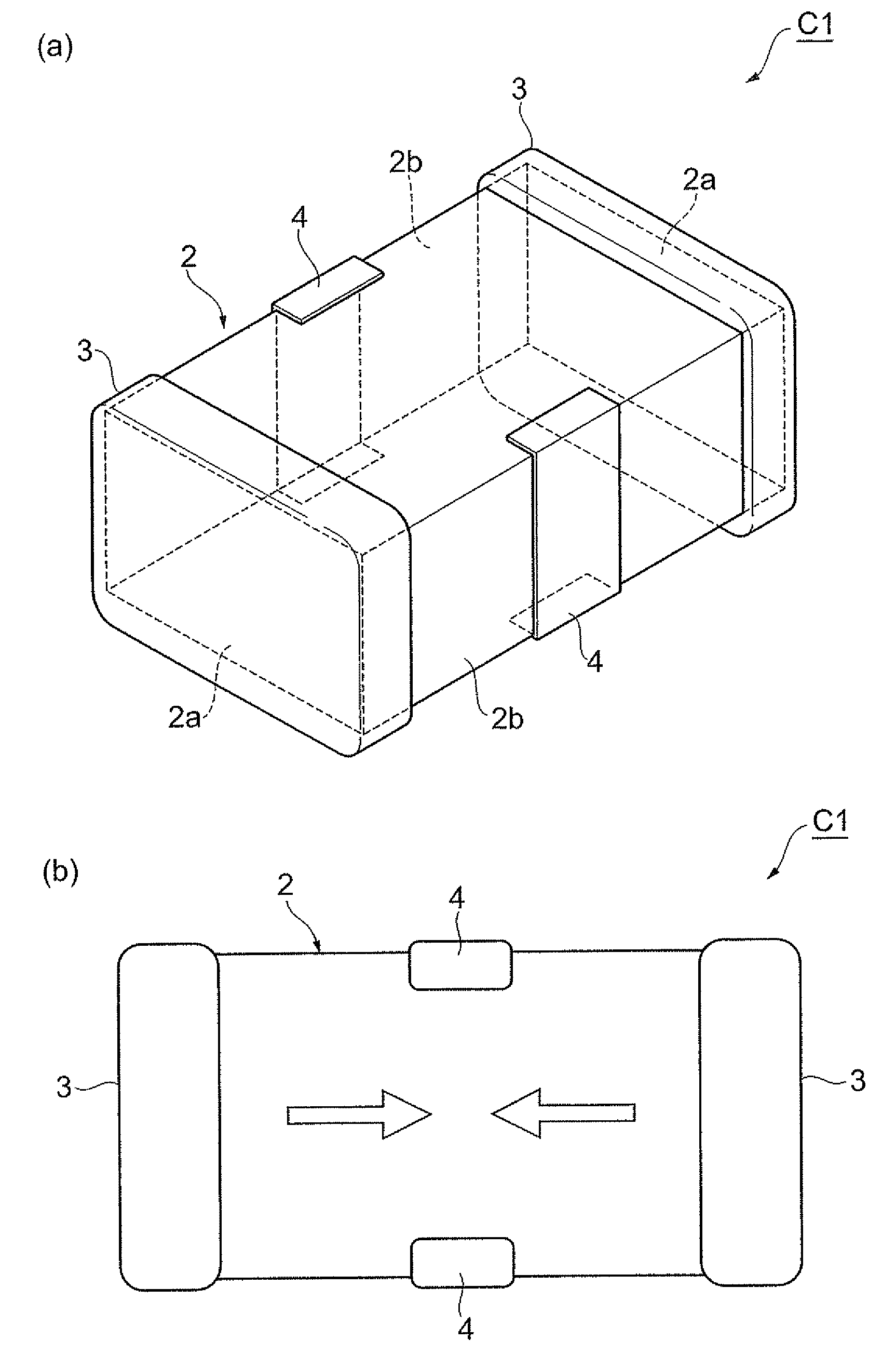
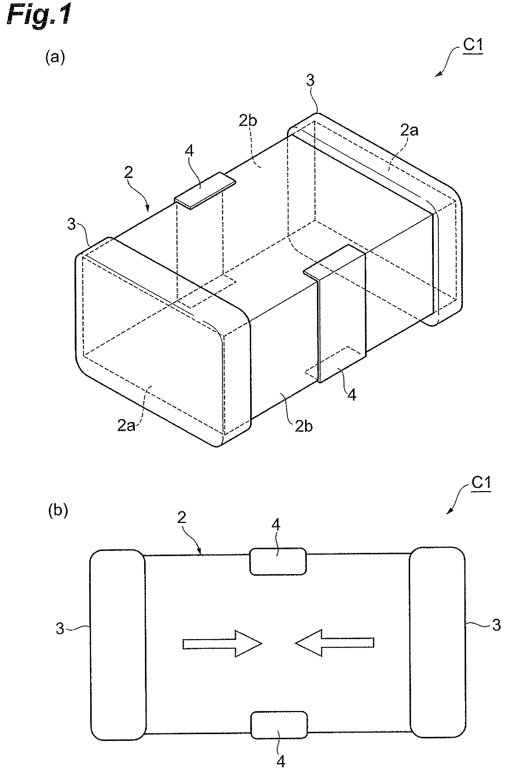
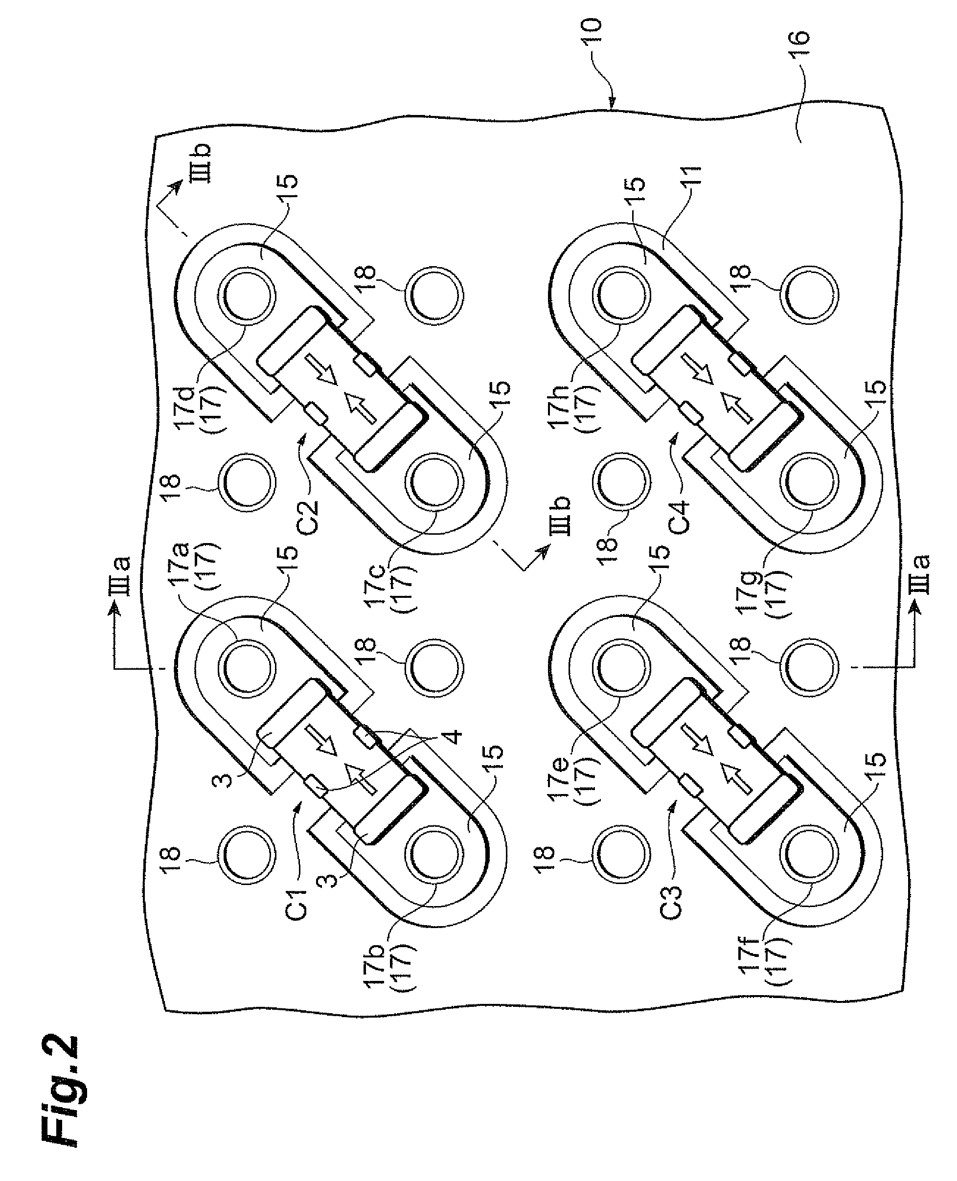
[0025]FIG. 1(a) is a perspective view of a feedthrough capacitor and FIG. 1(b) a top plan view of the feedthrough capacitor. FIG. 2 is a top plan view showing a feedthrough capacitor mounted structure according to the first embodiment. FIG. 3(a) is a sectional view along line IIIa-IIIa in FIG. 2 and FIG. 3(b) a sectional view along line IIIb-IIIb in FIG. 2. FIG. 2 is depicted without illustration of soldered portions between feedthrough capacitors and a substrate, for better viewing of the drawing.

[0026]The feedthrough capacitor mounted structure with feedthrough capacitors on the substrate according to the first embodiment will be described below with reference to FIGS. 1 to 3.

[0027]The feedthrough capacitor C1 is a so-called 3-terminal feedthrough capacitor. The feedthrough capacitor C1, as shown in FIG. 1(a), is constructed with a capacitor element body 2 of a nearly rectangular parallelepiped shape, a pair of terminal electrodes 3, and a pair of ground electrodes 4.

[0028]The ter...

second embodiment

[0042]The second embodiment will be described below based on FIG. 4. FIG. 4 is a top plan view showing a feedthrough capacitor mounted structure with feedthrough capacitors on a substrate according to the second embodiment. The feedthrough capacitors are soldered to the substrate in practice, but FIG. 4 is depicted without illustration of soldered portions between the feedthrough capacitors and the substrate, for better viewing of the drawing.

[0043]In the second embodiment, feedthrough capacitors C11, C12 are mounted on the mounting surface of the substrate 10. The feedthrough capacitors C11, C12 each have the same configuration as the feedthrough capacitor C1 in the first embodiment.

[0044]The feedthrough capacitor C11 is laid between a pair of power-side via holes 17 adjacent to each other in a direction intersecting with the row direction and also adjacent to each other in a direction intersecting with the column direction. The feedthrough capacitor C12 is laid between a pair of p...

third embodiment

[0051]The third embodiment will be described below based on FIG. 5. FIG. 5 is a top plan view showing a feedthrough capacitor mounted structure with feedthrough capacitors on a substrate according to the third embodiment. The feedthrough capacitors are soldered to the substrate in practice, but FIG. 5 is depicted without illustration of soldered portions between the feedthrough capacitors and the substrate, for better viewing of the drawing.

[0052]In the third embodiment, feedthrough capacitors C21-C24 are mounted on the mounting surface of the substrate 10. The feedthrough capacitors C21-C24 each have the same configuration as the feedthrough capacitor C1 in the first embodiment.

[0053]The feedthrough capacitor C21 is laid between a pair of power-side via holes 17a, 17b adjacent in an oblique direction. The terminal electrodes 3, 3 of the feedthrough capacitor C21 are connected to the respective power-side land electrodes 15 corresponding to the power-side via holes 17a, 17b.

[0054]T...


PUM


Abstract

A feedthrough capacitor having a pair of first terminal electrodes and a second terminal electrode is mounted on a mounting surface of a substrate. The substrate is an insulating substrate internally having first and second conductor portions isolated from each other, and has a plurality of first via holes, a plurality of second via holes, a plurality of first land electrodes, and a second land electrode. The first via holes and the second via holes, when viewed from the mounting surface side, are arranged in a matrix pattern and alternately arranged in a row direction and in a column direction. The feedthrough capacitor, when viewed from the mounting surface side, is located between a pair of said first via holes adjacent to each other in a direction intersecting with the row direction and also adjacent to each other in a direction intersecting with the column direction. The pair of first terminal electrodes are connected to the respective first land electrodes corresponding to the pair of adjacent first via holes. The second terminal electrode is connected to the second land electrode.

Description

BACKGROUND OF THE INVENTION[0001]1. Field of the Invention[0002]The present invention relates to a feedthrough capacitor mounted structure in which a feedthrough capacitor is mounted on a substrate.[0003]2. Related Background Art[0004]A known mounted structure of this type is the one described, for example, in Japanese Patent Application Laid-open No. 2007-129046. In the mounted structure described in No. 2007-129046, grid terminals are arranged in a matrix pattern on a multilayer substrate. A feedthrough capacitor is placed above one grid terminal and terminal electrodes of the feedthrough capacitor are soldered to respective grid terminals located around this one grid terminal.SUMMARY OF THE INVENTION[0005]In the mounted structure described in No. 2007-129046, the multilayer substrate has power-supply grid terminals and ground-electrode grid terminals as the grid terminals. The power-supply grid terminals and the ground-electrode grid terminals are alternately arranged in the row ...

Claims


Application Information

Patent Timeline
Patent Type & Authority Patents(United States)
IPC IPC(8): H01G4/35
CPCH01G4/232H01G4/35H05K1/0231H05K1/114H05K2201/10636H05K2201/10969Y02P70/50H01G2/02H01G4/38
Inventor TOGASHI, MASAAKI
Owner TDK CORPARATION
Why Eureka
Try Eureka