Dirt separator system for a vacuum cleaner

a separator system and vacuum cleaner technology, applied in the direction of suction hoses, cleaning filter means, suction cleaners, etc., can solve the problems of limited machinery space, increased cost and weight of vacuum cleaners, etc., and achieve the effect of reducing air flow losses and improving suction efficiency

Active Publication Date: 2011-02-08
AB ELECTROLUX
View PDF176 Cites 131 Cited by
  • Summary
  • Abstract
  • Description
  • Claims
  • Application Information

AI Technical Summary

Benefits of technology

[0005]It is an exemplary object of the invention to improve the suction efficiency by reducing the air flow losses in the air passages of a vacuum cleaner.
[0009]According to a fourth exemplary aspect of the invention, it is an object to improve the suction efficiency through the air passages of a vacuum cleaner having a cyclone-like type of debris collector. At least this object may be achieved by a vacuum cleaner according to claims 6, 7 and 8.

Problems solved by technology

In such a case it is not a preferred option to compensate for air flow losses in the air passages by increasing the motor power, since this will have the effect that the battery power will be used up in a shorter time, necessitating more frequent recharging.
As an alternative, the battery power capacity could be increased by providing more batteries in the vacuum cleaner, but this will have the effect that the costs and the weight of the vacuum cleaner also will increase.
As a consequence, the available space for the machinery is limited at the same time as the air must be drawn a comparatively long distance from the nozzle device in the lower end of the support body, through the air passages inside the same, and through the hand held unit.

Method used


Image

  • Dirt separator system for a vacuum cleaner
  • Dirt separator system for a vacuum cleaner
  • Dirt separator system for a vacuum cleaner

Examples


Embodiment Construction

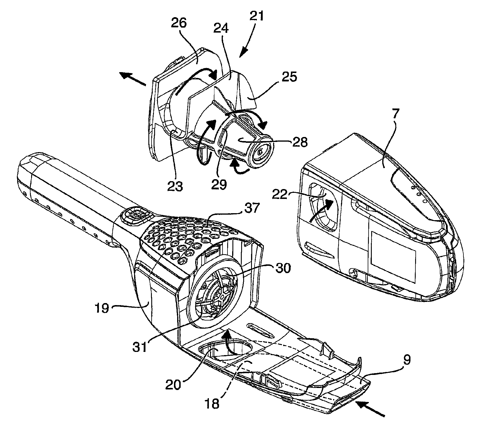
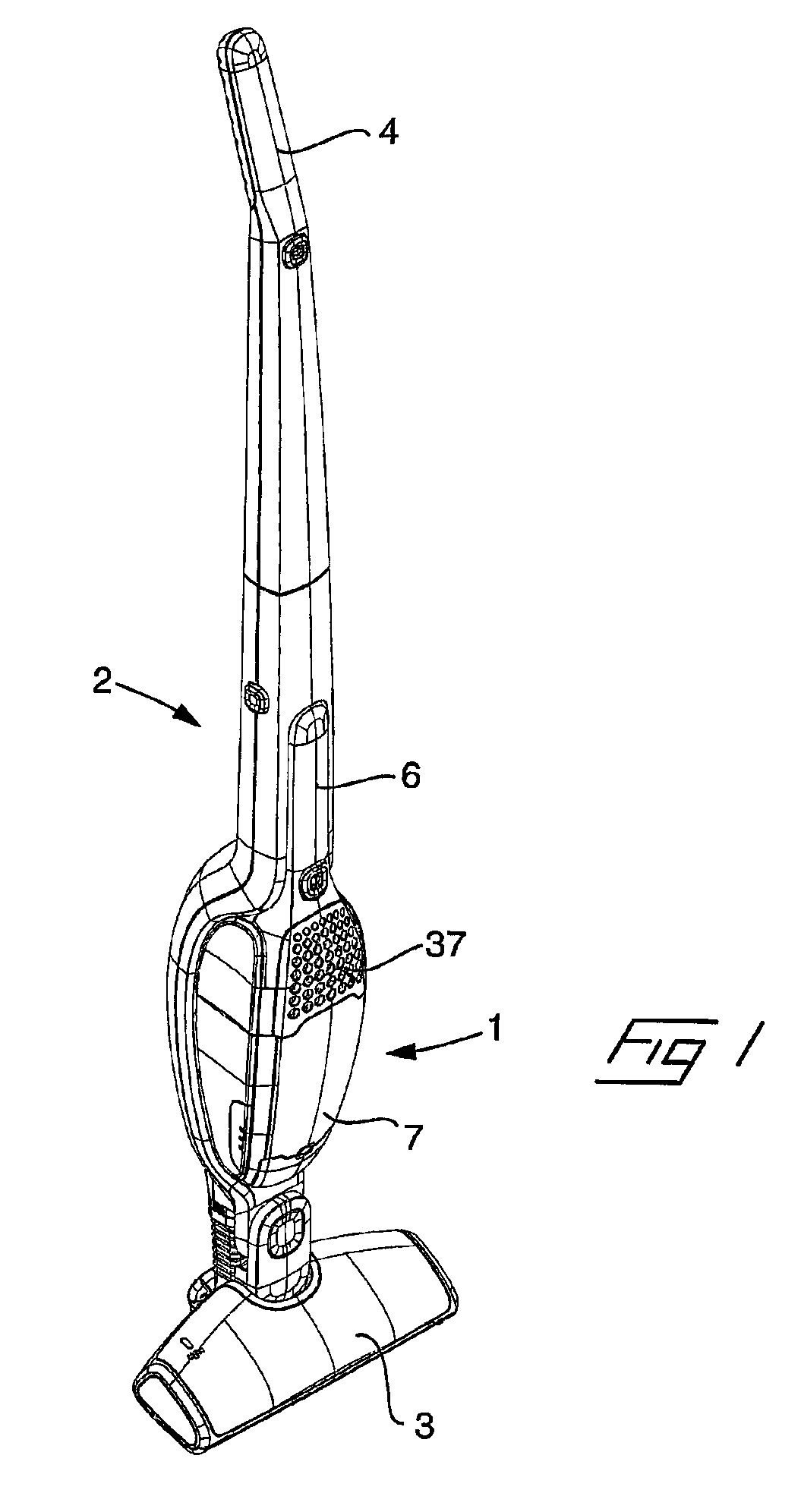
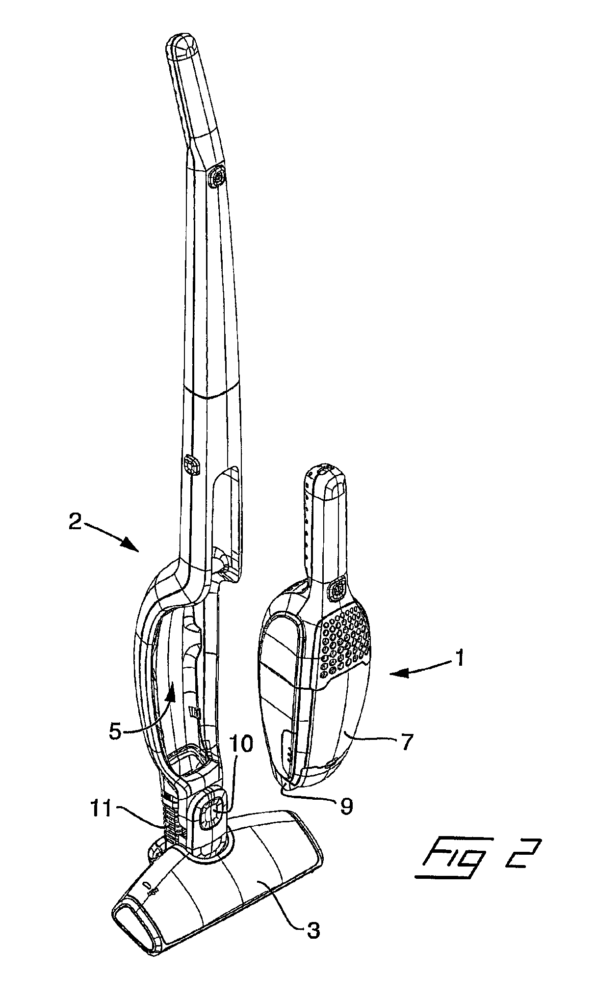
[0021]A vacuum cleaner of a 2-in-1 type, is shown in FIG. 1 in an assembled state and in FIG. 2 with a hand held unit 1 released from a stick-formed support body 2. The support body 2 comprises a nozzle device 3 in a lower end, a handle 4 in an upper end, and a recess 5 for accommodating the hand held unit 1. The hand held unit comprises an electrical motor, chargeable batteries, a fan unit driven by the electrical motor, a handle 6 and a cyclone-like separator including a debris container 7 for collecting debris and dust. The nozzle device 3 is of an ordinary, previously known kind, by means of which floors can be vacuum cleaned when the hand held unit 1 is inserted in the support body 2, in which case air is drawn by the fan unit from the nozzle device 3, through an air passage 8 in the support body 2, and into the hand held unit. When, on the other hand, the hand held unit is released from the support body, the hand held unit can be used separately to vacuum clean, for example, t...


PUM


Abstract

A vacuum cleaner having an elongated support body, a nozzle attached to a lower end of the elongated support body by an articulated joint, a motor, a fan unit, a debris container, and an air passage that extends from the nozzle device, past the articulated joint by a flexible hose and to an air passage in the support body. The flexible hose is formed with a generally rectangular cross section.

Description

[0001]The invention relates to improvements in vacuum cleaners in order to reduce air flow losses in air passages through a vacuum cleaner.BACKGROUND OF THE INVENTION[0002]The suction efficiency of a vacuum cleaner is determined, besides by the effective power of the electric motor, also to a large extent by the suction effect losses or air flow losses in the air passages through the vacuum cleaner.[0003]Avoiding air flow losses in the air passages is important in all kinds of vacuum cleaners in order to achieve a high suction efficiency and reduce energy consumption. However, it is especially important in vacuum cleaners having an electrical motor powered by batteries. In such a case it is not a preferred option to compensate for air flow losses in the air passages by increasing the motor power, since this will have the effect that the battery power will be used up in a shorter time, necessitating more frequent recharging. As an alternative, the battery power capacity could be incr...

Claims


Application Information

Patent Timeline
Patent Type & Authority Patents(United States)
IPC IPC(8): A47L9/16
CPCA47L5/225A47L5/24A47L9/248A47L9/0081A47L9/165A47L5/32A47L5/28A47L9/24
Inventor BESKOW, JONASMIEFALK, HAKANDANESTAD, ULRIK
Owner AB ELECTROLUX
Why Eureka
Try Eureka