Exhaust pipe structure

a technology of exhaust pipe and pipe body, which is applied in the direction of machines/engines, cycles, transportation and packaging, etc., can solve the problems of increasing length and difficulty in ensuring a space for placing the elongated exhaust pipe or the enlarged exhaust chamber, and achieves the effect of restricting the overall dimension

Active Publication Date: 2011-02-08
HONDA MOTOR CO LTD
View PDF12 Cites 11 Cited by
  • Summary
  • Abstract
  • Description
  • Claims
  • Application Information

AI Technical Summary

Benefits of technology

[0012]According to an embodiment of the present invention, the adjustment range for the engine characteristics can be made wider in comparison to the case in which the exhaust-gas inlet is placed closer to the exhaust port than the exhaust-gas is placed. This is made possible because both of the upstream-side exhaust pipe and the downstream-side exhaust pipe can be elongated while the length of the exhaust pipe structure as a whole in the front-to-rear direction is restricted.
[0013]According to an embodiment of the present invention, an adequate volume of the exhaust chamber can be secured because the space behind the lower end frame that extends obliquely upwardly and rearwardly can be used efficiently as a space for placement of the exhaust chamber.
[0014]According to an embodiment of the present invention, the adjustment range for engine characteristics can be made wider by elongating the upstream-side exhaust pipe, because the upstream-side exhaust pipe can be curved as being convex outwards of the vehicle body.
[0015]In an embodiment of the present invention, the inward diagonal section and the outward diagonal section project outwardly of the vehicle body in only a restricted amount in the crossing part of these sections when viewed from the bottom of the vehicle body. As a result, the rider can plant his / her foot more easily on the ground because the space on which the passenger can put his / her foot becomes wider below the rider's seat.

Problems solved by technology

These measures, however, accompany an increase in the length of the exhaust pipe as a whole in the front-to-rear direction, and an enlargement of the dimension of the exhaust chamber, so that it is sometimes difficult to secure a space for placing the elongated exhaust pipe or the enlarged exhaust chamber.

Method used


Image

  • Exhaust pipe structure
  • Exhaust pipe structure
  • Exhaust pipe structure

Examples


Embodiment Construction

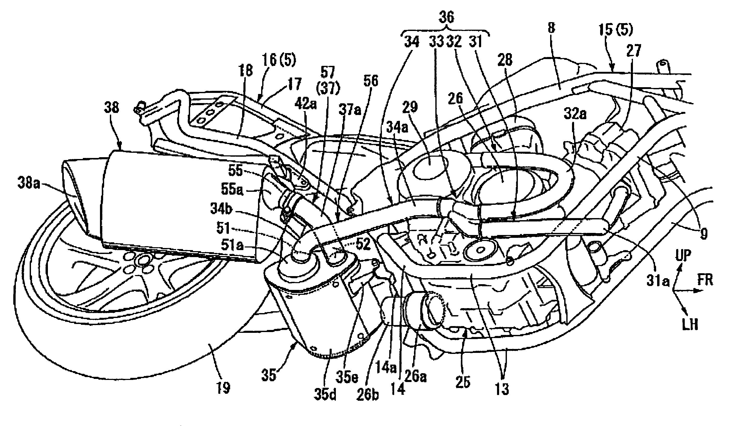
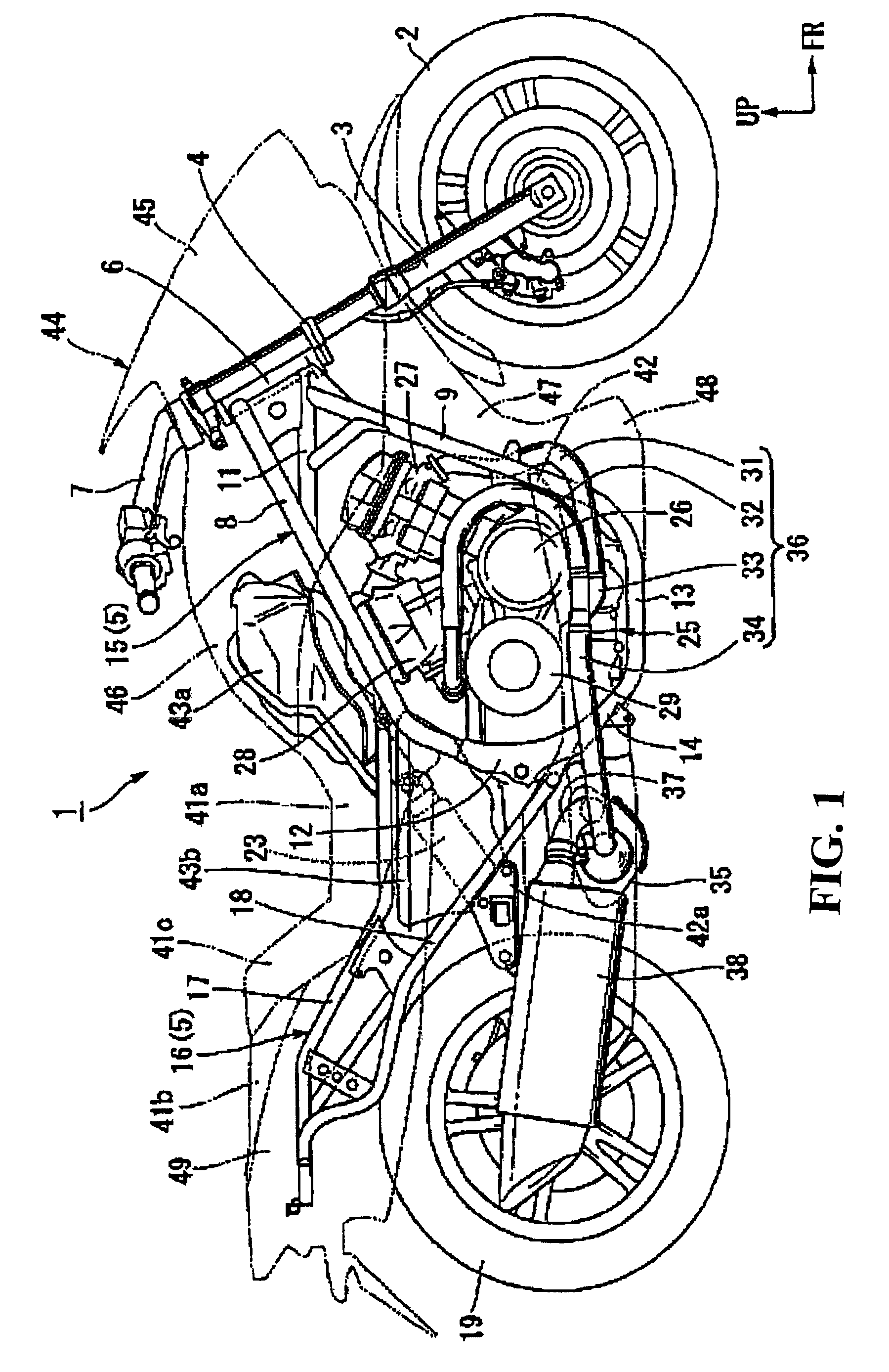
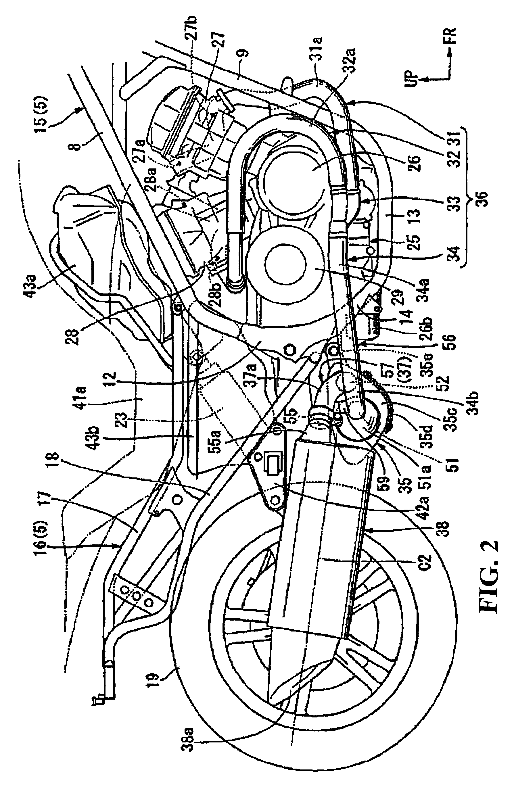
[0025]Hereinbelow, descriptions will be given as to an embodiment of the present invention with reference to the drawings. In the descriptions below, directions with respect to front, rear, right, left and the like are the same as those in the vehicle unless otherwise indicated. In the drawings, an arrow FR points to the front of the vehicle, an arrow LH points to the left-handed direction of the vehicle, and an arrow UP points to the upward direction of the vehicle.

[0026]As shown in FIG. 1, a front wheel 2 of a saddle-ride type motorcycle 1 is rotatably supported by a right and left pair of bottom end portions of a front fork 3. The upper portion of each front fork 3 is pivotally and steerably supported by a head pipe 6 at the front-end portion of a body frame 5, with a steering stem 4. A handlebar 7 for steering the front wheel is attached to the upper portion of the steering stem 4. A right and left pair of main frames 8 extend obliquely downwardly and rearwardly from the upper p...


PUM


Abstract

To provide an exhaust pipe structure in which the length of the exhaust pipe can be elongated while the total dimension is restricted. Provided is an exhaust pipe structure which includes an upstream-side exhaust pipe connected to exhaust ports of an engine. An exhaust chamber is provided which has an exhaust-gas inlet and an exhaust-gas outlet, and in which the upstream-side exhaust pipe is connected to the exhaust-gas inlet. In addition, the exhaust pipe structure includes a downstream-side exhaust pipe which is connected to the exhaust-gas outlet and which extends in such a direction as to move away from the exhaust ports. In the exhaust pipe structure, the exhaust-gas inlet is formed at a position farther away from the exhaust ports than the exhaust-gas outlet is positioned.

Description

CROSS-REFERENCE TO RELATED APPLICATIONS[0001]The present application claims priority under 35 USC 119 to Japanese Patent Application No. 2006-151206 filed on May 31, 2006 the entire contents of which are hereby incorporated by reference.BACKGROUND OF THE INVENTION[0002]1. Field of the Invention[0003]The present invention relates to an exhaust pipe structure for vehicles such as motorcycles.[0004]2. Description of Background Art[0005]An exhaust pipe structure is known wherein an exhaust chamber is provided somewhere along the exhaust pipe extending in the front-to-rear direction of vehicle, with an exhaust-gas inlet formed at the front side of the exhaust chamber and an exhaust-gas outlet formed at the rear side. See, for example, Japanese Utility Model Application Laid-Open No. Sho 60-18839.[0006]In the above-mentioned exhaust pipe structure, for the purpose of making a change in engine characteristics (particularly, engine power) depends linearly on the throttle opening angle. Poss...

Claims


Application Information

Patent Timeline
Patent Type & Authority Patents(United States)
IPC IPC(8): F01N1/00B62M7/02F01N1/08F01N13/08F02B67/00
CPCF01N3/2885F01N13/02
Inventor YAMAKURA, YUTAKAAMINO, HIDEOSHIBUKAWA, TAKERO
Owner HONDA MOTOR CO LTD
Why Eureka
Try Eureka