

Damping force generator for hydraulic shock absorber
a technology of hydraulic shock absorber and generator, which is applied in the direction of shock absorbers, steering devices, cycle equipment, etc., can solve the problems of small adjustable range of damping force and difficulty in reducing damping force of damping valve, and achieves small amount of deflection, reduce damping force of damping valve, and high valve stiffness.
- Summary
- Abstract
- Description
- Claims
- Application Information
AI Technical Summary
Benefits of technology
Problems solved by technology
Method used
Image

Examples
first embodiment
(First Embodiment) (FIGS. 1 to 9)
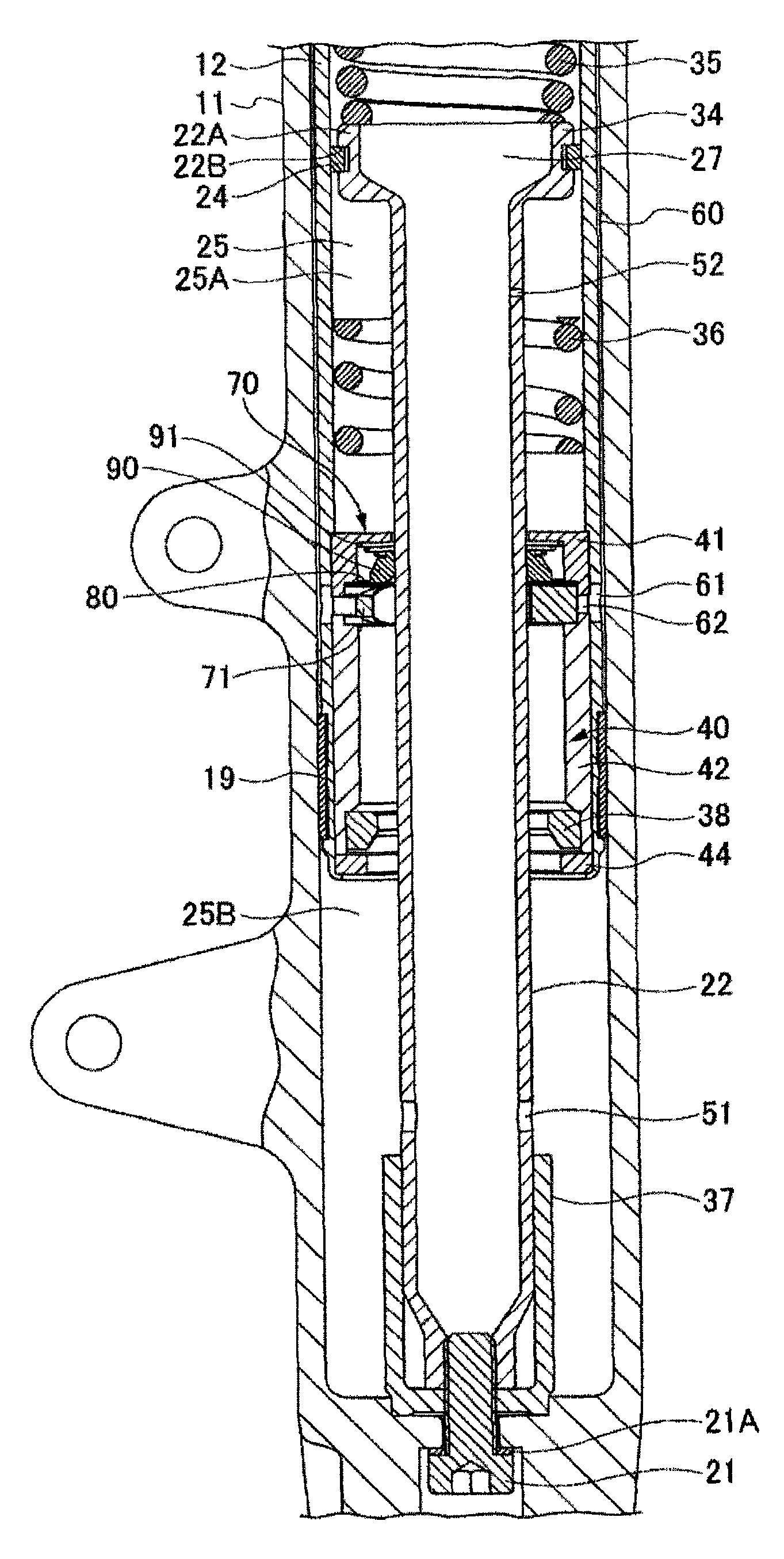
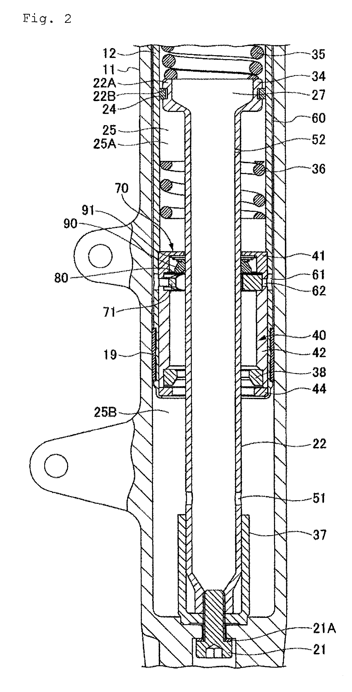
[0022]As shown in FIGS. 1 to 3, a front fork 10 (hydraulic shock absorber), which is used on a two-wheel vehicle or the like, has an outer tube 11 (wheel-side tube) having a closed end on the wheel side and an open end on the other side and an inner tube 12 (body-side tube) on the vehicle body side slidably inserted into the outer tube 11. Provided at the open end of the outer tube 11 where the inner tube 12 is inserted are a slide guide 13, a seal spacer 14, an oil seal 15, a stopper ring 16, and a dust seal 17. A slide guide 19 is attached to the lower end outer periphery of the inner tube 12, which is inserted into the outer tube 11.
[0023]A bolt 21 is inserted through a bottom of the outer tube 11 with a copper packing 21A fitted in between, and a hollow pipe 22 is installed upright secured by the bolt 21. The bolt 21 is screwed into a threaded inner periphery of a reduced diameter portion below a tapered lower end portion of the hollow pipe 22. A...
second embodiment
(Second Embodiment) (FIG. 10, FIG. 11)
[0054]A second embodiment as illustrated in FIG. 10 and FIG. 11 differs from the first embodiment shown in FIGS. 1 to 9 in that the ring-shaped member 90R of the compression-stroke check valve 90 is provided with slit passages 90A through which the oil flows from the upper oil chamber 25A to the lower oil chamber 25B during the extension stroke.
[0055]In this embodiment, a large number of slit passages 90A are formed at a plurality of circumferential positions at fixed intervals in the outer periphery of the ring-shaped member 90R of the compression-stroke check valve 90 where the compression-stroke check valve 90 is not seated on the upper surface of the inner periphery of the extension-stroke damping valve 80.
[0056]According to this embodiment, a damping force with a linear-proportional characteristic caused by the passage resistance in the slit passages 90A may be obtained via the process of the oil in the upper oil chamber 25A pushing open th...
third embodiment
(Third Embodiment) (FIG. 12, FIG. 13)
[0057]A third embodiment as illustrated in FIG. 12 and FIG. 13 differs from the first embodiment shown in FIGS. 1 to 9 in that a lower damping force generator 100 is also provided. The lower damping force generator 100 is disposed between the lower oil chamber 25B and the upper oil chamber 25A around the hollow pipe 22 (and the holes 61 formed in the inner tube 12 and communicating with the annular interspace chamber 60). The lower damping force generator 100 allows the oil to flow into the lower oil chamber 25B during the extension stroke and creates a passage resistance to the oil flowing out of the lower oil chamber 25B during the compression stroke.
[0058]The lower damping force generator 100, which shares the valve seat 71 of the first embodiment, has a compression-stroke damping valve 110, an extension-stroke check valve 120, and a valve spring 121 stacked in this order on the lower oil chamber 25B side of the valve seat 71 secured to the pi...
PUM
 Abstract
Description
Claims
Application Information