Air flow path for an air impingement finger duct

a finger duct and air flow technology, which is applied in the field of ramps, can solve the problems of difficult to acquire a uniform velocity and/or mass flow of air along the length of the duct, adversely affect the uniformity of cooking and oven efficiency, and increase the energy cost of operating the oven, so as to increase the airflow efficiency

Inactive Publication Date: 2011-02-08
LINCOLN FOODSERVICE PRODS
View PDF36 Cites 1 Cited by
  • Summary
  • Abstract
  • Description
  • Claims
  • Application Information

AI Technical Summary

Benefits of technology

[0008]The present disclosure serves these and other purposes with a multi-tapered ramp channel concept to force air mass flow to the columniating plate and cover plate in a substantially uniform manner, where low airflow pressures may otherwise have existed along the length of the duct. This is a corrective enhancement to the duct to significantly increase its airflow efficiency.
[0009]The ramps are formed as channels to guide the airflow through the length of the duct. The air entering the duct that interacts with the ramp channel is directed to the columniating and cover plates, as opposed to flowing directly to the end of the duct, while the rest of the air entering the duct passes along its normal course. This direction change is what improves the airflow volume and pressure out of the dispensing orifices in the cover plate, in an area that would typically exhibit lowered pressure without the enhancements of the present disclosure.

Problems solved by technology

In situations where a lower profile or reduced height oven is preferred, this presents a problem because it is more difficult to acquire a uniform velocity and / or mass flow of air along the length of the duct.
This phenomenon can adversely affect uniformity of cooking and efficiency of the oven, as well as increase the energy costs of operating the oven.

Method used


Image

  • Air flow path for an air impingement finger duct
  • Air flow path for an air impingement finger duct
  • Air flow path for an air impingement finger duct

Examples


Embodiment Construction

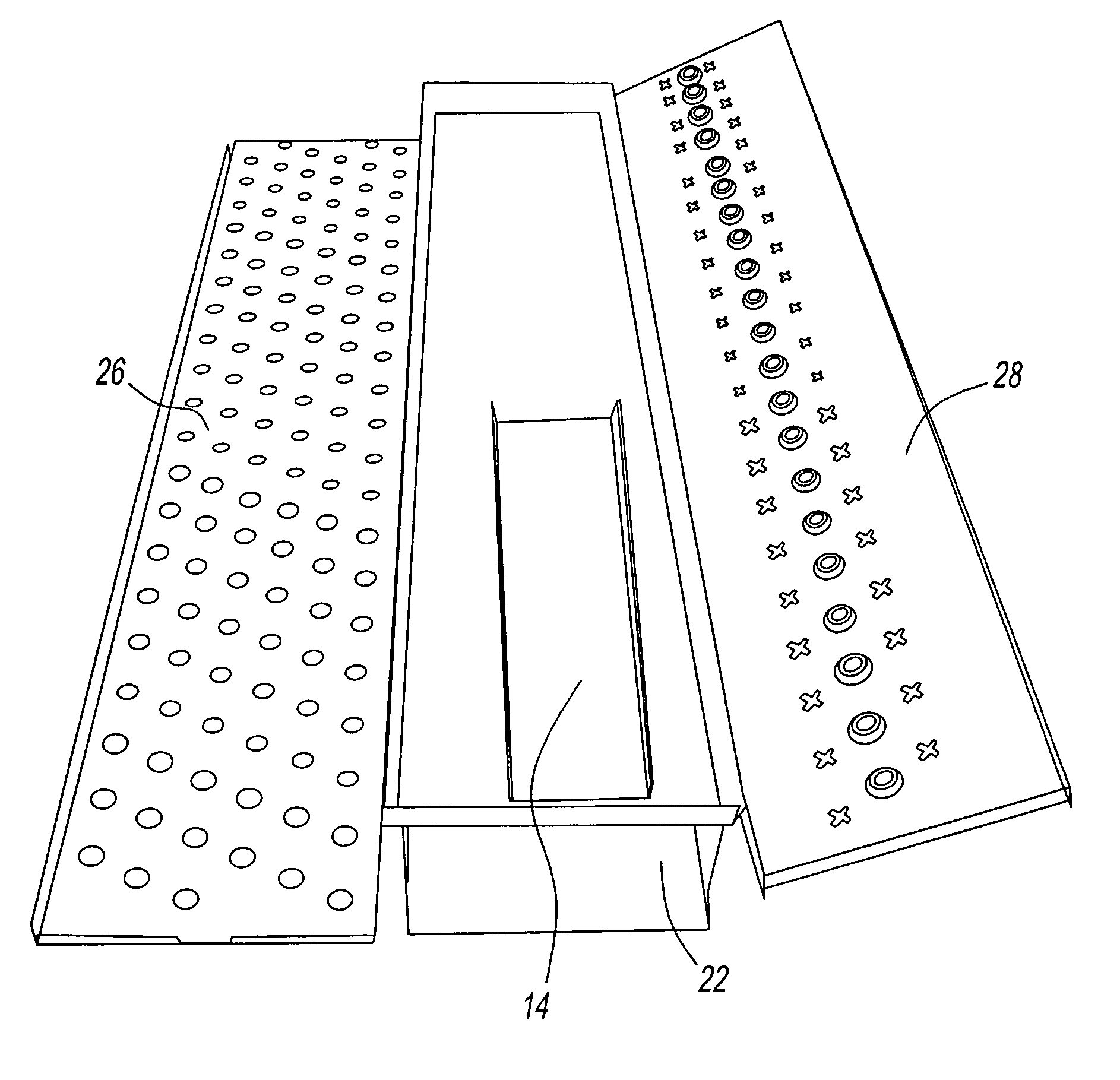
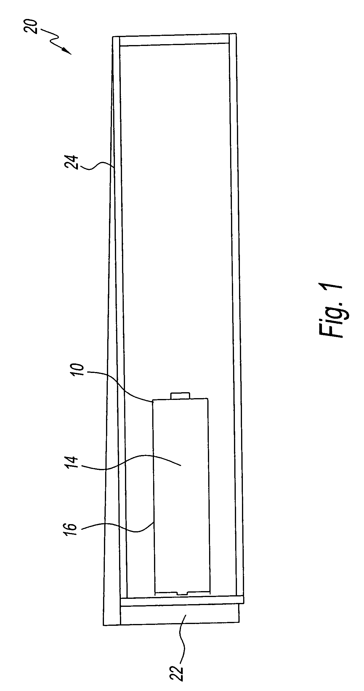
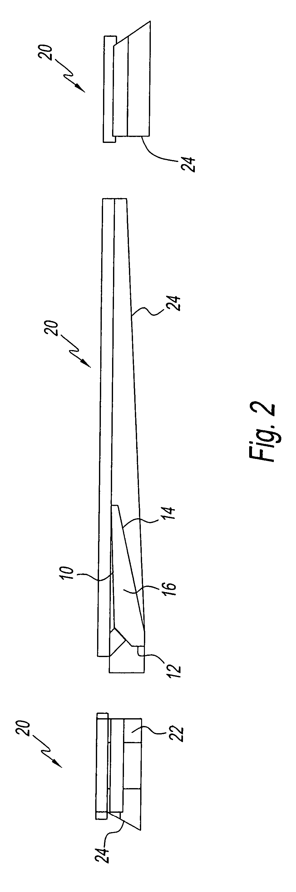
[0022]The present disclosure provides a significant improvement over currently available devices in terms of cooking uniformity and heat transfer over the entire cooking surface. By enhancing the velocity and mass flow of air along the length of the duct, the ramp channel of the present disclosure ensures that the disparities in cooking uniformity along the cooking surface are minimized, if not completely eliminated. This improved airflow design also helps to increase the energy efficiency of the oven, which saves significantly on the energy costs associated with currently available models.

[0023]The ramp channel of the present disclosure is multi-tapered so that air entering the duct is redirected toward the columniating plate and cover plate of the dispensing duct. The ramp channel can be placed at a position along the length of the duct that would otherwise experience lower air pressure. Thus, air or mass flow entering the duct which would normally move to the end of the duct and ...


PUM


Abstract

An impinging air duct that comprises one or more ramps disposed within. The ramps direct air entering the duct through columnating orifices, and helps to provide an even flow of air out of the orifices, along the length of the duct. The angle of the ramp and the location of the ramp within the duct can be adjustable.

Description

CROSS-REFERENCE TO RELATED APPLICATIONS[0001]The present disclosure claims priority to U.S. Provisional Application No. 60 / 842,244, filed on Sep. 5, 2006.BACKGROUND OF THE DISCLOSURE[0002]1. Field of the Disclosure[0003]The present disclosure relates to a device for improving airflow inside an impinging air duct. More particularly, the present disclosure relates to a ramp channel that balances the air pressure along the length of the duct.[0004]2. Description of the Related Art[0005]In the field of impinging air ovens and other devices, an air duct is a tapered, horizontal airflow delivery device disposed above and / or below the cooking surface. The duct becomes dynamically pressurized and moves and directs airflow toward jet-forming orifices disposed in a columniating plate. These orifices then direct the airflow toward a cover plate with a second pattern of orifices or dispensing ducts. Such tapered ducts are well known in the field.[0006]The size and shape of the ducts will have t...

Claims


Application Information

Patent Timeline
Patent Type & Authority Patents(United States)
IPC IPC(8): F15D1/02
CPCF15D1/0005F15D1/04
Inventor HENKE, MITCHELL C.
Owner LINCOLN FOODSERVICE PRODS
Why Eureka
Try Eureka