
Optical blood gas sensor for real time measurement

a technology of optical blood gas and real-time measurement, applied in the field of sensors, can solve the problems of unsuitable continuous intrusion-type measurements, unsuitable electrodes for carbon dioxide sensing, and user discomfort, and achieve the effects of stable sensing, easy and non-intrusive measurement methods, and easy implementation of continuous measurements

Inactive Publication Date: 2011-02-08
CHUNG YUAN CHRISTIAN UNIVERSITY
View PDF2 Cites 2 Cited by
  • Summary
  • Abstract
  • Description
  • Claims
  • Application Information

AI Technical Summary

Benefits of technology

The optical gas concentration sensor provides a cost-effective, compact, and non-intrusive method for continuous monitoring of carbon dioxide levels, improving mobility and comfort, making it suitable for home care use while maintaining high accuracy.

Problems solved by technology

Conventional electrodes for sensing the concentration of carbon dioxide, for example a biomedical sensing system called i-STAT® available from Abbott Laboratories, U.S.A., are very accurate but expensive.
Moreover, there are problems such as gas content in blood may be consumed during measurement and their size being large, making them unsuitable for continuous intrusion-type measurements.
Since the size of the overall sensing system is usually bulky, they are not suitable for home care use, and may cause discomfort to users.
Mobility and accuracy in measurement are also affected.

Method used


Image

  • Optical blood gas sensor for real time measurement
  • Optical blood gas sensor for real time measurement
  • Optical blood gas sensor for real time measurement

Examples


first embodiment

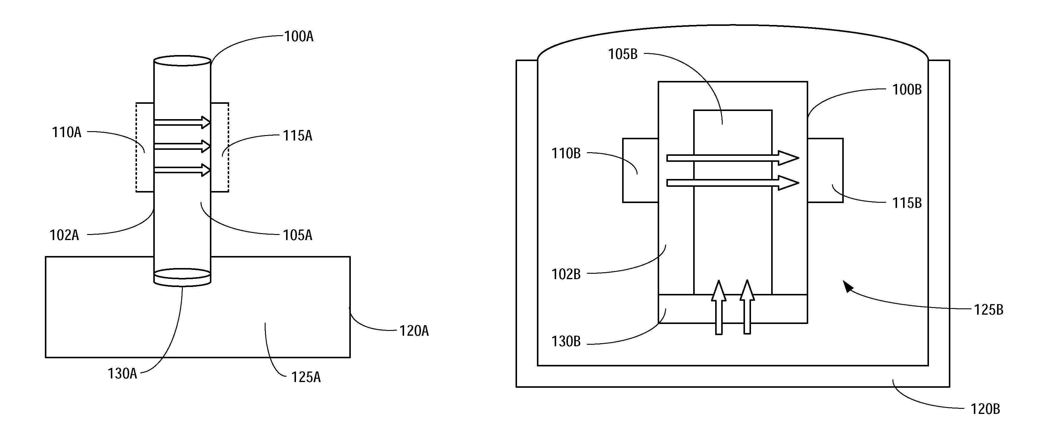
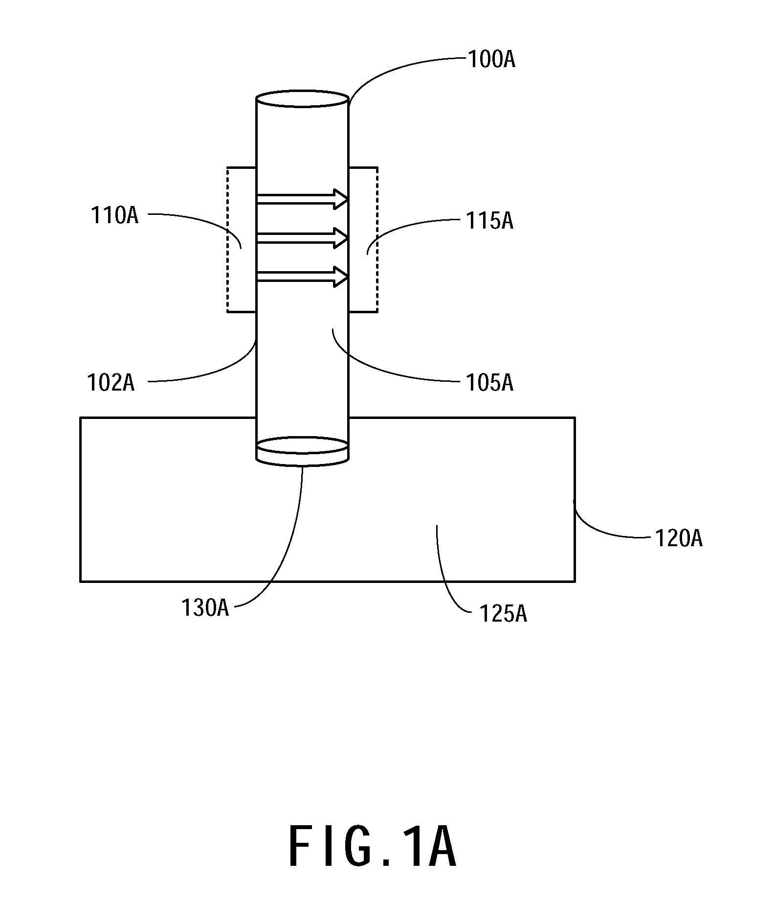
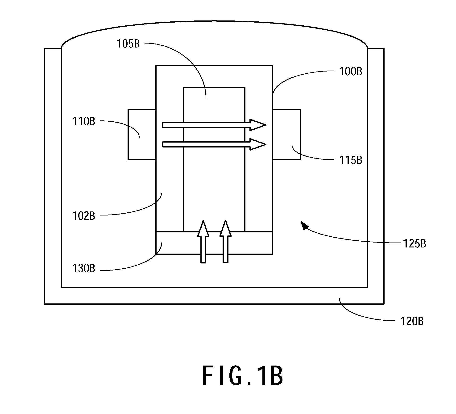
[0018]the present invention discloses an optical gas concentration sensor, including a gas filtering device, an indicator, a light source and a photo detector. A gas contained in a liquid inside a container diffuses into the gas filtering device in which the indicator resides. The indicator then reacts with the gas diffused into the gas filtering device, and changes its color as a result of the reaction. The light source provided on one side of the gas filtering device is used to emit light through the reacted indicator. The photo detector is located on the other side of the gas filtering device, wherein the light source and the photo detector are on opposite sides of the gas filtering device. The photo detector receives the light that passes through the reacted indicator, and outputs a sensing signal according to the intensity of the received light, thereby determining pH variation of the liquid.

[0019]In this embodiment, the gas filtering device may include a light filter. The ligh...

second embodiment

[0023]the present invention discloses a method for optically sensing gas concentration. As shown in FIG. 2A, first, a portion of a gas filtering device is placed in the liquid in a container, wherein the gas filtering device includes a gas filtering membrane and an indicator, such that a gas in the liquid diffuses into the gas filtering device through the gas filtering membrane and contacts the indicator. Then, a light source is irradiated on the gas filtering device. A photo detector then receives the light transmitted through the gas filtering device emitted by the light source. Thereafter, the concentration of the gas is determined based on the intensity of the light received by the photo detector.

[0024]In a preferred embodiment of the present invention, as shown in FIG. 2B, the method for optically sensing gas concentration further includes a step of using a dynamic flow device to replace the indicator already reacted with the gas in the optical path between the light source and...


PUM

PropertyMeasurementUnit
wavelengthaaaaaaaaaa
pHaaaaaaaaaa
pHaaaaaaaaaa

Abstract

An optical gas concentration sensor and method for measuring blood gas based on the light adsorption sensing technique are disclosed. The optical gas concentration sensor comprises a light source, a photo detector, and a gas filtering membrane for separating the indicator and a liquid. A gas in the liquid diffuses to the indicator through the gas filtering membrane so as to change the color of the indicator due to the chemical reaction occurred between the indicator and the gas. Then, the photo detector receives the light passing though the reacted indicator from the light source. The gas concentration is determined based on pH-sensitive absorbance spectrum of the indicator.

Description

BACKGROUND OF THE INVENTION[0001]1. Field of the Invention[0002]The present invention generally relates to sensors, especially an optical gas concentration sensor.[0003]2. Description of the Prior Art[0004]Blood analyzers help patients manage their own health conditions in a more cost-effective and convenient way before seeking a doctor for further diagnosis and treatment. Not only can patients monitor their health conditions by checking the densities of eight major parameters whenever they wish, but the information can also be provided to the doctors to facilitate diagnosis. When measuring the concentration of carbon dioxide, sensors that can provide stable and continuous measurements are needed.[0005]Conventional electrodes for sensing the concentration of carbon dioxide, for example a biomedical sensing system called i-STAT® available from Abbott Laboratories, U.S.A., are very accurate but expensive. Moreover, there are problems such as gas content in blood may be consumed during...

Claims


Application Information

Patent Timeline
Patent Type & Authority Patents(United States)
IPC IPC(8): G01J1/48
CPCG01N21/783
Inventor HSIUNG, SHEN-KANCHOU, JUNG-CHUANSUN, TAI-PINGCHOU, NIEN-HSUANLAI, CHIH-WEI
Owner CHUNG YUAN CHRISTIAN UNIVERSITY
Learn More