Input device, and multi-function peripheral

a multi-functional, input device technology, applied in the direction of electronic switching, pulse technique, instruments, etc., can solve the problems of complex arrangement of electrostatic sensors, mechanical switches described above, and defective switches

Active Publication Date: 2011-02-08
BROTHER KOGYO KK
View PDF11 Cites 0 Cited by
  • Summary
  • Abstract
  • Description
  • Claims
  • Application Information

AI Technical Summary

Benefits of technology

[0010]The present invention was made in an effort to solve the problems described above. It is therefore a first object of the present invention to provide an input device which has a simple arrangement and which permits easy recognition or determination of a pressing operation and a sliding operation. A second object is to provide a multi-function peripheral provided with such an input device.
[0014]In the multi-function peripheral according to the second aspect of this invention, the electrode surface is formed at the corner portion of the main body housing which includes the corresponding corner edge of the surface of the main body housing on which the image display portion or at least one operation control portion is disposed. Accordingly, the pressing and sliding operations of the electrically charged body can be easily performed with respect to the electrode disposed on the electrode surface.

Problems solved by technology

The mechanical switches described above tend to be defective due to contamination with dust and dirt deposited on and around them.
Namely, the plurality of electrodes and the detecting IC must be connected to each other, leading to a problem of complicated arrangement of the electrostatic sensors.

Method used


Image

  • Input device, and multi-function peripheral
  • Input device, and multi-function peripheral
  • Input device, and multi-function peripheral

Examples


first embodiment

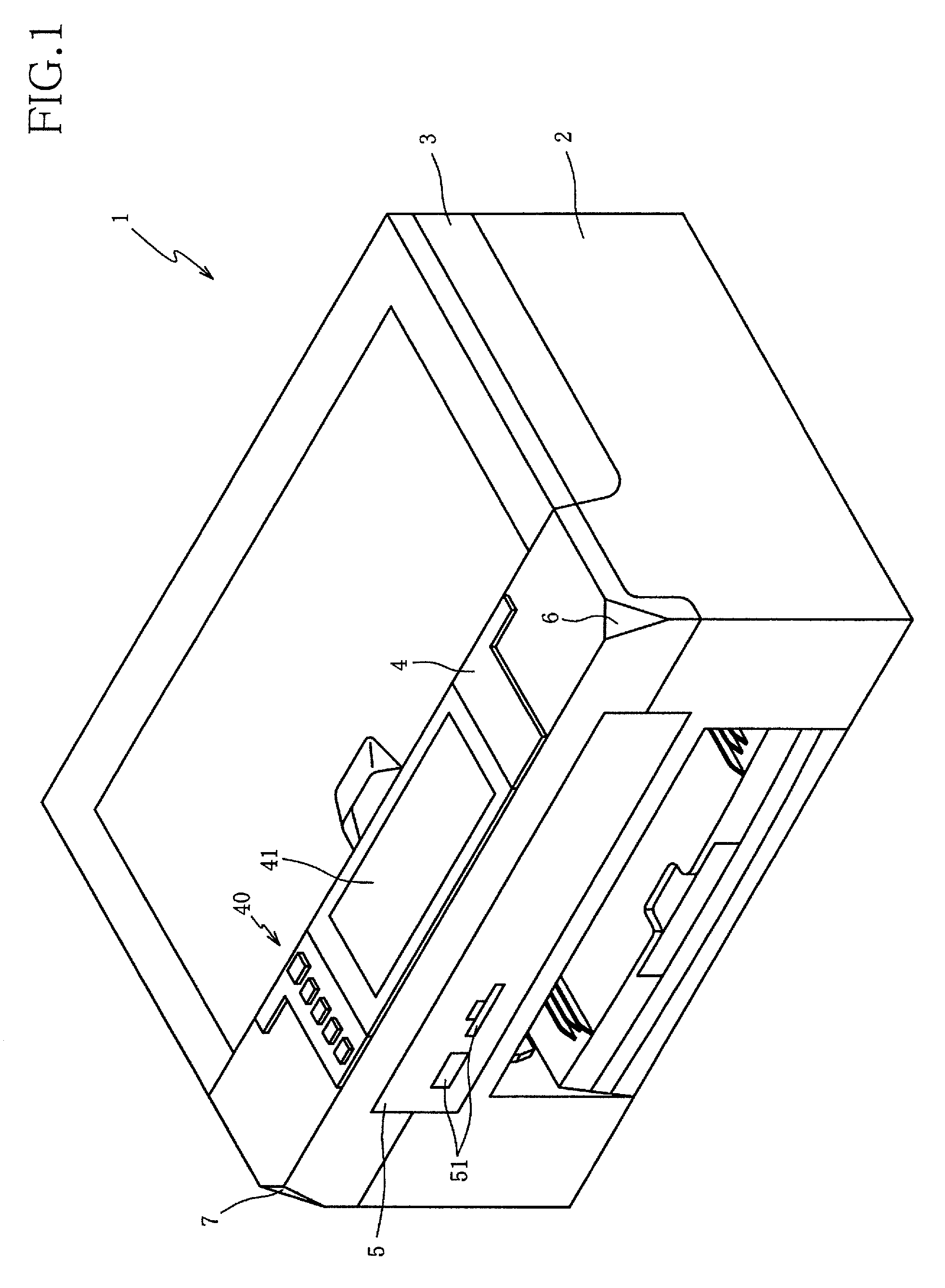
[0030]Preferred embodiments of the present invention will be described by reference to the drawings. The perspective view of FIG. 1 shows an arrangement of a multi-function peripheral 1 (hereinafter abbreviated as “MFP 1”) constructed according to this invention.

[0031]The MFP 1 has a plurality of functions including a telephone function, a facsimile (telecopier) function, a printing function and a copying function. In particular, this MFP 1 is characterized by an input device which has a simple arrangement and which permits easy recognition or determination of a pressing operation and a sliding operation.

[0032]The MFP 1 has a generally box construction, incorporating a printer 2 in its lower part, a scanner 3 in its upper part, an operation panel 4 in front of the scanner 3, and a slot portion 5 disposed below the operation panel 4 and in the front surface of a main body housing of box construction of the MFP 1. The printer 2 is configured to print images on a recording medium such ...

second embodiment

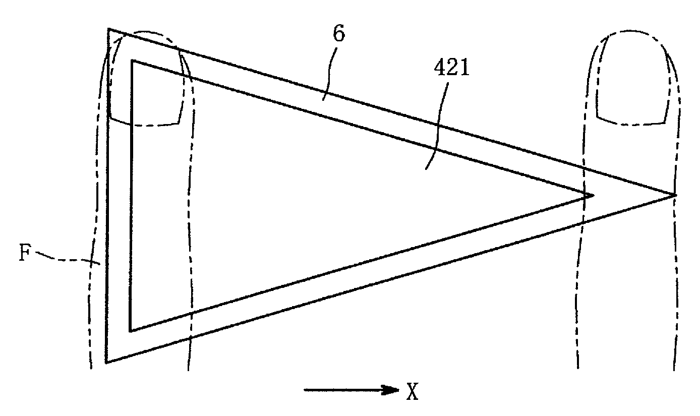
[0094]As shown in FIG. 9A, the first electrode 424 consists of an elliptical first region 424a located on the left side as seen in FIG. 9A, an elliptical second region 424b located on the right side and having a smaller size than the first region 424a, and a connecting region 424c connecting the elliptical first and second regions 424a, 424b to each other. The second electrode in the second embodiment has the same shape as the first electrode.

[0095]To begin with, a sliding operation of the operator's finger F with respect to the first electrode 424 in the first direction (indicated by the arrow-headed line X) will be described.

[0096]During an initial portion of the sliding operation in the first direction, the output value of the output signal of the detecting IC 423 changes as indicated by a solid line I indicated in FIG. 8B. In the initial portion of the sliding operation in the first direction, the output value decreases to a predetermined value as the right side surface of the f...


PUM


Abstract

An input device including an electrode a width dimension of which changes in its direction of extension, an output portion an output signal of which corresponds to an electrostatic capacity induced between the electrode and an electrically charged body when the body approaches or touches the electrode, a detecting portion to detect a change of an output signal value of the output portion, and an operation recognizing portion configured to recognize, on the basis of the detected change of the output signal value, one of a pressing operation and a sliding operation of the body performed with respect to the electrode, wherein the pressing operation is performed by a moving action of the body in which the body approaches or touches the electrode, while the sliding operation is performed by a sliding action of the body in the direction of extension of the electrode while the body is held in close proximity to or in touch with the electrode.

Description

CROSS REFERENCE TO RELATED APPLICATION[0001]The present application claims the priority from Japanese Patent Application No. 2008-221670 filed Aug. 29, 2008, the disclosure of which is herein incorporated by reference in its entirety.BACKGROUND OF THE INVENTION[0002]1. Field of the Invention[0003]The present invention relates to an input device, and a multi-function peripheral provided with the input device.[0004]2. Description of Related Art[0005]There is known an input device including mechanical switches such as pushbuttons and sliding keys, and a CPU (central processing unit) which is connected to the pushbuttons and sliding keys and configured to detect pressing operations of the pushbuttons and sliding operations of the sliding keys.[0006]JP-2008-105333 A discloses (in paragraph [0045] and FIGS. 1 and 2, in particular) a printer 1 including such an input device provided with a power-on pushbutton 12 disposed on a main body housing, and a control portion 41 configured to detect...

Claims


Application Information

Patent Timeline
Patent Type & Authority Patents(United States)
IPC IPC(8): H03K17/96
CPCG06F3/03547G06F3/044H03K17/962G06F2203/0339H03K2017/9604H03K2217/94052H03K2217/96066G06F3/0448
Inventor YAMAGUCHI, RYOJI
Owner BROTHER KOGYO KK
Why Eureka
Try Eureka