Radial compression mechanism

a compression mechanism and radial technology, applied in the direction of forging/pressing/hammering apparatus, prosthesis, manufacturing tools, etc., can solve the problems of large gap between the wedges, metal struts of the stent can move into the gap and be damaged, and typically does not provide a sufficiently accurate positional relationship of the wedge-shaped working end, so as to achieve a large usable size range

Active Publication Date: 2011-02-15
GOFF ED +2
View PDF3 Cites 22 Cited by
  • Summary
  • Abstract
  • Description
  • Claims
  • Application Information

AI Technical Summary

Benefits of technology

[0010]Another object of the invention is to provide a new and improved radial compres

Problems solved by technology

A shortcoming of this type of mechanism is that there exists a gap between adjacent wedges, the size of which varies with the diameter of the cavity in an undesirable way.
The strict design tradeoffs for this type of mechanism results in a mechanism that must be large to provide a small maximum gap for a given diameter range, or a mechanism that must have a large gap to provide the same diameter range in a small size.
Large gaps between the wedges are a disadvantage because they allow space for parts of the compressed device to go into.
For example, the

Method used


Image

  • Radial compression mechanism
  • Radial compression mechanism
  • Radial compression mechanism

Examples


Embodiment Construction

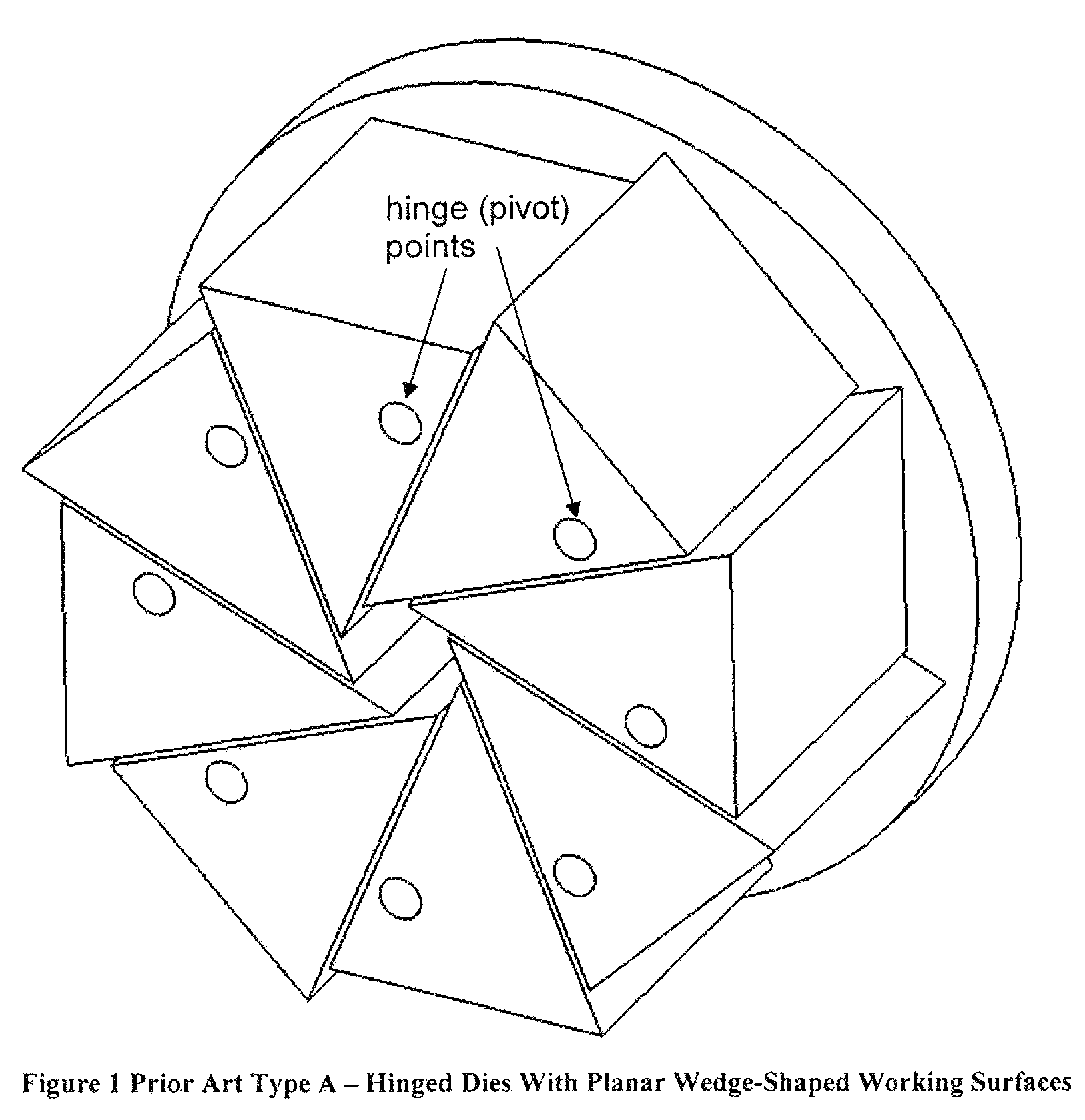
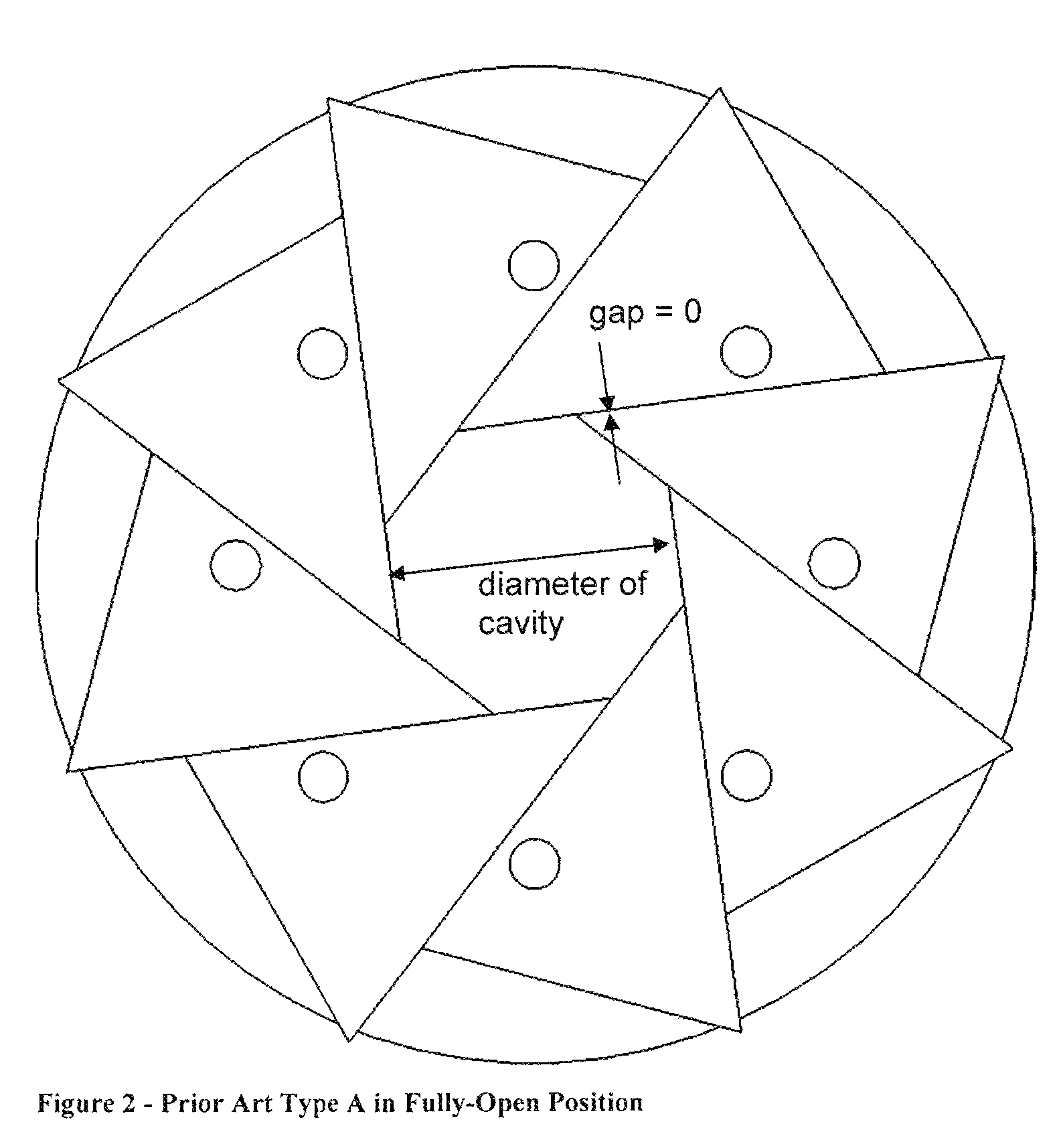
[0037]Turning now to the drawings, FIGS. 1-4 illustrate an embodiment of the first type of prior art radial compression mechanism that is described in detail above in the Background of the Invention. FIGS. 6-9 illustrate an embodiment of the second type of prior art radial compression mechanism with linear movement of the die, also described in detail above in the Background of the Invention. FIGS. 11-14 illustrate an embodiment of the third type of prior art radial compression mechanism described in detail above in the Background of the Invention. Each of these types of devices operates in a known manner and will not be further discussed herein.

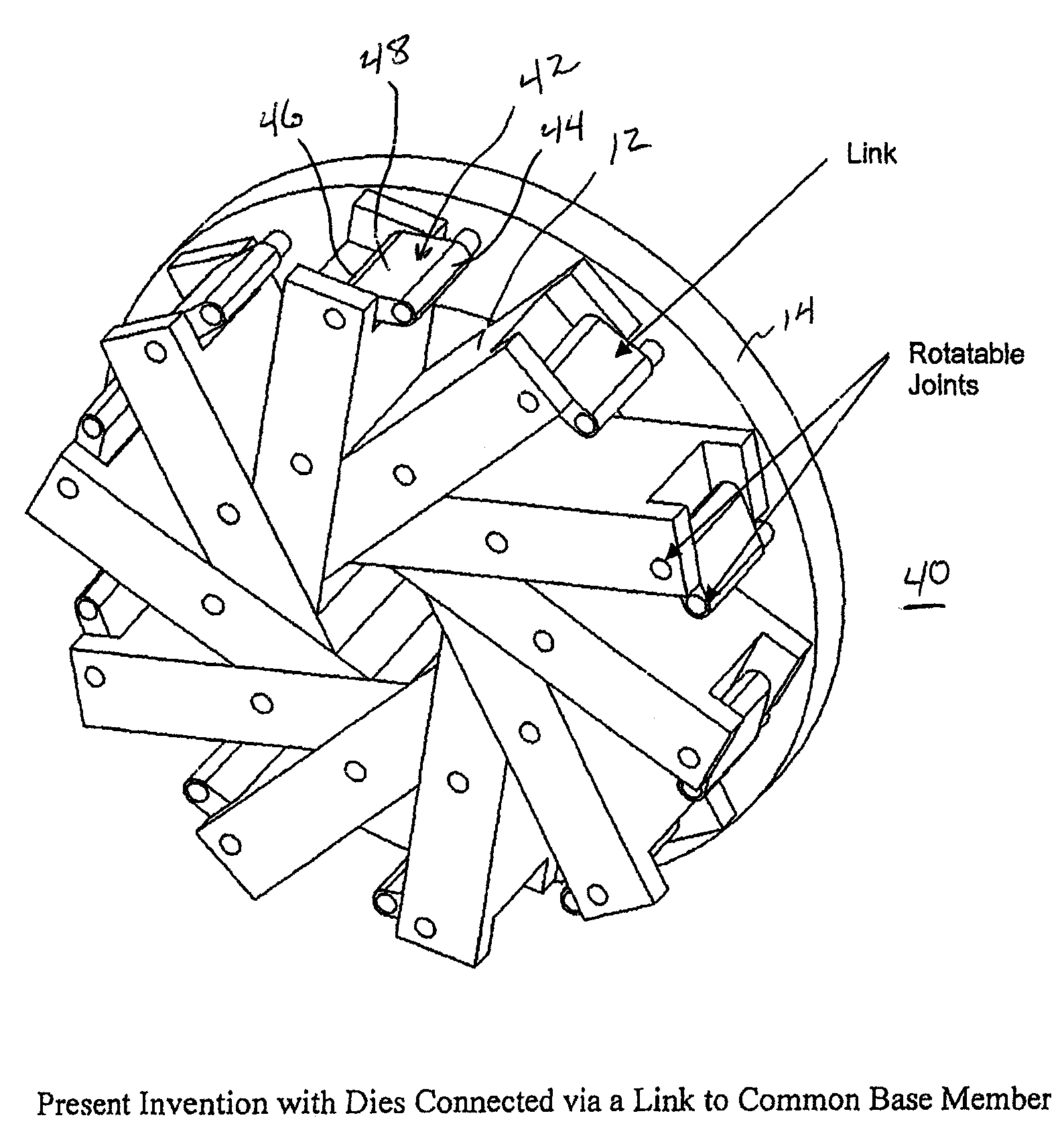
[0038]Turning now to FIGS. 16 through 21, attention is directed to FIG. 16 which illustrates a radial compression mechanism in accordance with the present invention, generally designated 10. Mechanism 10 includes a plurality of compression dies 12 carried by a base member 14. Each die 12 is of a generally identical wedge shape, and is arrang...


PUM

PropertyMeasurementUnit
Forceaaaaaaaaaa
Diameteraaaaaaaaaa
Lengthaaaaaaaaaa

Abstract

Radial compression mechanism includes a base member and a plurality of elongated compression dies. The dies are arranged in a generally circular orientation on the base member with a contact surface of each die in sliding contact with a base surface of an adjacent die. A portion of each base surface of each die cooperates with portions of base surfaces of adjacent dies to define a generally cylindrical central cavity moved between open and closed positions by a driving mechanism. The dies are cammingly coupled to the base member and to the driving mechanism so that rotation of the driving mechanism about the central axis causes each die to move generally arcuately about a point of camming engagement with the base member.

Description

CROSS-REFERENCE TO RELATED APPLICATION[0001]This application claims the benefit of U.S. Provisional Application No. 60 / 888,662, filed 7 Feb. 2007.FIELD OF THE INVENTION[0002]This invention generally relates to radial compression mechanisms and more specifically to mechanisms for radially compressing devices such as stents, catheters, balloons, and the like.BACKGROUND OF THE INVENTION[0003]In the manufacture and testing of medical devices, mechanisms are used to radially compress cylindrical devices such as stents, balloons, and catheters. For example, installation of a stent into a catheter balloon is typically done by compressing the stent radially inward onto the balloon with enough pressure to permanently deform the stent to a smaller diameter and to slightly embed the metal stent into the plastic balloon. In another example, a polymer catheter balloon is compressed radially after pleating to wrap it tightly around the catheter shaft. In another example, a self-expanding stent is...

Claims


Application Information

Patent Timeline
IPC IPC(8): B30B7/04B21J7/16B21D41/04
CPCB21J9/06B30B7/04A61F2002/9522Y10T29/49927Y10T29/53996Y10T29/5367Y10T29/49913A61F2/9522
Inventor GOFF, EDWARRINER, JEREMIAH J.KNIGHT, JUSTIN
Owner GOFF ED
Why Eureka
Try Eureka