Traction enhanced controlled pressure flexible flat tension member termination device

a flexible, controlled pressure technology, applied in the direction of lifters, snap fasteners, buckles, etc., can solve the problem of increasing friction

Inactive Publication Date: 2011-02-15
OTIS ELEVATOR CO
View PDF52 Cites 5 Cited by
  • Summary
  • Abstract
  • Description
  • Claims
  • Application Information

AI Technical Summary

Benefits of technology

[0009]The termination of the invention further optionally includes a jamming device attachable to the cut end of the tension member. In the unlikely event of tension member slippage through the termination device, the jamming device will be drawn into the termination device and will prevent the tension member cut end from pulling through the termination device.

Problems solved by technology

Friction is increased by texturing the surfaces of the termination device with which the tension member makes contact.

Method used


Image

  • Traction enhanced controlled pressure flexible flat tension member termination device
  • Traction enhanced controlled pressure flexible flat tension member termination device
  • Traction enhanced controlled pressure flexible flat tension member termination device

Examples


example ii

[0066]Tension member plates are 190 mm long[0067]30 mm wide

[0068]⁢LOAD⁢⁢SIDEPressure=NA=12320⁢⁢N30.190=2.16⁢⁢MPa=313⁢⁢psi_⁢⁢(LOAD)⁢CUT⁢⁢SIDE=3.78⁢⁢MPa⁢⁢548⁢⁢psi_⁢⁢(CUT)⁢21560⁢⁢N30.190

In This Example the Pressure Exerted on the Tension Member is Acceptable for Both Sides of the Termination Device. Thus, Plates are Long Enough.

Bolt Torque Calculations (For First Example Only):

example i

125 mm Plates with 8 Bolts

[0069]LOAD⁢⁢PER⁢⁢BOLTN1=N2=11⁢,000⁢⁢NLOAD⁢⁢PER⁢⁢BOLT=11,0008=1375⁢⁢N

[0070]Bolt Size / Threads:[0071]M8-8 mm course thread Pitch=1.25

Prop Class 8.8

[0072]Bossard Catalog Table, Preload Torque

[0073]

PRELOADTORQUE17,050N24N − MBOSSARD CATALOGSo for 1,540N1540(24) = 2.17N − M17,050

[0074]T=⁢0.2⁢⁢F⁢⁢ι⁢⁢d=⁢0.2⁢⁢(1540)⁢8=2.5⁢⁢N⁢-⁢Mwhere⁢⁢F⁢⁢ι=1540⁢⁢N⁢⁢and⁢⁢d=8⁢⁢mm

Plate Dimensional Calculations

[0075]I⁢316⁢⁢PLATE=1⁢(316)312=.0005493⁢″(1⁢⁢inch⁢⁢strip)⁢5.4931×10⁻⁴Δ=5⁢⁢wl4384⁢⁢EII14=1⁢(.25)312=.001302Δ=5⁢(425)⁢(1.653)4384⁢(3×10⁷)⁢(.0005493)1.302×10⁻³⁢⁢in4_Δ=.002507⁢⁢in_if⁢⁢Δ=P⁢⁢l348⁢⁢EI=425⁢⁢(1.181)⁢⁢1.653348⁢⁢(5.493×10⁻³)⁢(3×10⁷)=.002866⁢⁢in⁢_⁢(316)∼=McI=[145.159]⁢.18752.0005493=-13.608.0005493Uniform⁢⁢Dist.⁢Load24,774⁢⁢psiM⁢⁢max⁢⁢wl28⁢425⁢⁢(1.653)28=145.159

Uniform Dist. Load.

[0076]⁢∼14=McI=[145.159_]⁡[2.50_]1.302+10-3=13,935⁢⁢psi

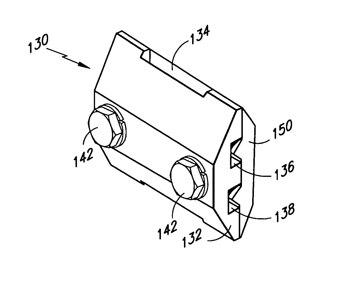
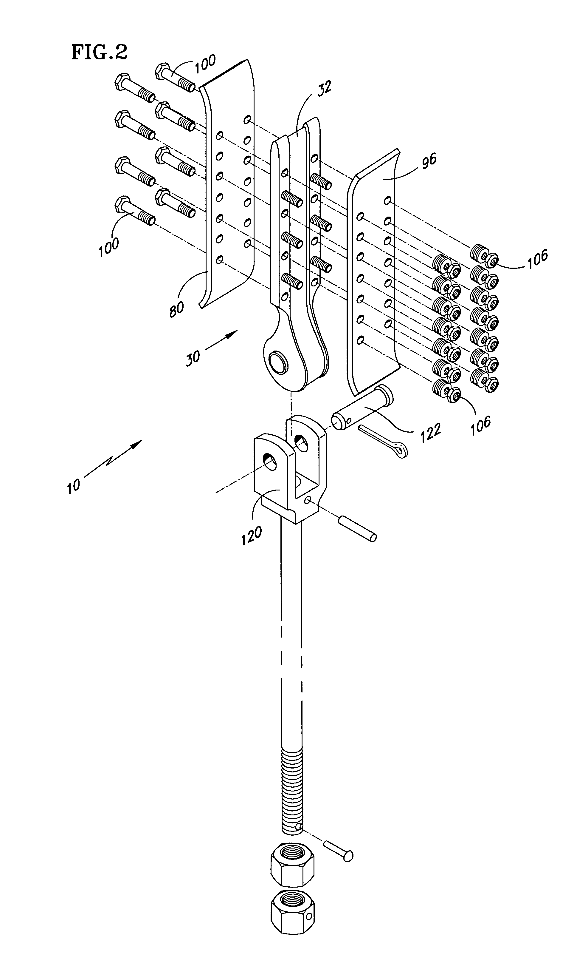
[0077]Referring to FIG. 15, a clevis is illustrated. Clevis 120 is seen connected to the termination assembly in FIG. 2 (in exploded condition). ...


PUM


Abstract

A tension member termination device optimized for terminating flexible flat tension members, the device including a socket with a compression portion and a bulbous portion and a compression plate on each side of the compression portion fastenable by fasteners extending through all of these feature. The device provides a pathway for the tension member through the device and upon torquing the fasteners reliably secures the tension member while avoiding deleterious pressure and stress therein.
The invention also provides a safety clamp for optional use with the invention.

Description

[0001]This application is a divisional of U.S. patent application Ser. No. 09 / 218,989, filed Dec. 22, 1998 now U.S. Pat. No. 6,820,726.TECHNICAL FIELD[0002]The present invention relates to elevator systems. More particularly the invention relates to a termination for a flexible flat tension member.BACKGROUND OF THE INVENTION[0003]A conventional traction elevator system includes a car, a counterweight, two or more ropes (tension members) interconnecting the car and counterweights; terminations for each end of the ropes at the connection points with the car and counterweights, a traction sheave to move the ropes and a machine to rotate the traction sheave. The ropes have traditionally been formed of laid or twisted steel wire which are easily and reliably terminated by means such as compression terminations and potted terminations.[0004]Compression type terminations for steel ropes of larger diameters (conventional steel elevator ropes) are extremely effective and reliable. The range ...

Claims


Application Information

Patent Timeline
Patent Type & Authority Patents(United States)
IPC IPC(8): B66B7/00B66B7/08
CPCB66B7/085Y10T24/3958
Inventor ERICSON, RICHARD J.O'DONNELL, HUGH J.MELLO, ARY O.BARRETT, DALE R.REHMER, DENNIS J.
Owner OTIS ELEVATOR CO
Why Eureka
Try Eureka