Viscous friction clutch for driving a cooling fan in a motor vehicle

a technology of friction clutches and cooling fans, which is applied in the direction of clutches, fluid couplings, gearing, etc., can solve the problems of undesirable start-up of cooling fans, unsatisfactory noise, unnecessary energy consumption,

Active Publication Date: 2011-02-15
MAHLE INT GMBH
View PDF24 Cites 24 Cited by
  • Summary
  • Abstract
  • Description
  • Claims
  • Application Information

AI Technical Summary

Benefits of technology

[0011]The inventive measures in the form of a storage volume in the supply chamber have particularly advantageous effects in electromagnetically controlled clutches because the valve in the supply chamber is open while the clutch is at standstill and the magnetic coil is currentless.
[0012]Embodiments of the invention are illustrated in the figures and are described in greater detail below. The figures show:
[0013]FIGS. 1-4, a first embodiment of the invention in the form of an annular supply chamber with a storage chamber that is divided in the circumferential direction, in various angular positions;
[0014]FIG. 5, a second embodiment of the invention in the form of a viscous friction clutch with an axially divided annular supply chamber;
[0015]FIG. 6, the viscous friction clutch according to FIG. 5 in the form of an axial section, and
[0016]FIG. 7, a speed diagram for the cold start performance of a conventional clutch and a clutch according to the clutch invention.

Problems solved by technology

Such a start-up is undesirable when the internal combustion engine is cold, and causes undesirable noise as well as unnecessary energy consumption.
As mentioned above, this clutch also has the disadvantage that oil can flow from the supply chamber into the working chamber while the clutch is at standstill, so that an undesirable start-up of the cooling fan can take place when the clutch is restarted.

Method used


Image

  • Viscous friction clutch for driving a cooling fan in a motor vehicle
  • Viscous friction clutch for driving a cooling fan in a motor vehicle
  • Viscous friction clutch for driving a cooling fan in a motor vehicle

Examples


Embodiment Construction

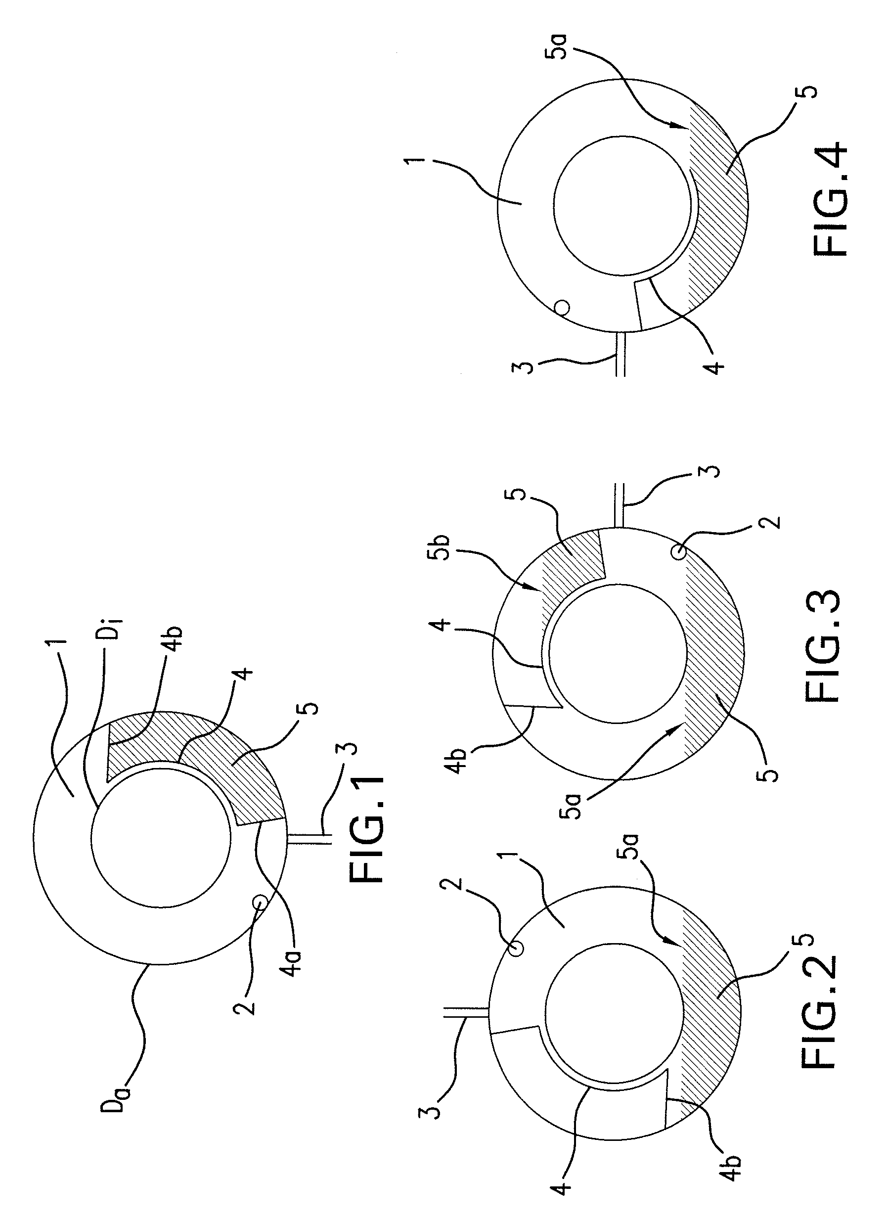
[0017]FIG. 1 shows a schematic representation of an annular supply chamber 1 of a not-shown viscous friction clutch, which can correspond to the initially-described state of the art. The annular supply chamber 1 is arranged in a not-shown driving disk or primary disk of the not-shown viscous friction clutch, and therefore is driven with the drive speed of the internal combustion engine, i.e., without slip. The supply chamber 1 has an outside diameter Da and an inside diameter Di. A supply bore 2 and a return bore 3 are arranged in the region of the outside diameter Da and form part of a not-shown device for supplying silicone oil situated in the supply chamber to a not-shown working chamber of the viscous friction clutch, as well as a corresponding device for returning the silicone oil from the working chamber to the supply chamber 1. In the embodiment shown, the return bore 3 is situated in a lower position or the so-called 6 o'clock position. The supply bore 2 is arranged in the i...


PUM


Abstract

A viscous friction clutch for driving a cooling fan in a motor vehicle is disclosed, wherein the viscous friction clutch comprises a driving disk and a housing, a supply chamber and a working chamber, a device for supplying shear fluid from the supply chamber to the working chamber and a device for returning the shear fluid from the working chamber to the supply chamber.

Description

BACKGROUND OF THE INVENTION[0001]The invention pertains to a viscous friction clutch according to the preamble of Claim 1 for driving a cooling fan in a motor vehicle.[0002]Viscous friction clutches or so-called viscous clutches are known and preferably used as fan clutches for driving a cooling fan in motor vehicles. The cooling fan is driven by the internal combustion engine of the motor vehicle via the friction clutch, wherein it is known to realize a temperature-dependent control with the aid of a bimetal or electromagnetic control in dependence on various parameters such as, e.g., the coolant temperature. In viscous friction clutches, the torque in a working chamber is transmitted by shearing a shear fluid, for example, commercially available silicone oil. The silicone oil circulates between a supply chamber and the working chamber with the aid of a controlled supply device and a return device. The filling level of the working chamber defines the transmittable torque.[0003]The ...

Claims


Application Information

Patent Timeline
Patent Type & Authority Patents(United States)
IPC IPC(8): F16H35/02
CPCF16D35/024
Inventor SCHULTHEISS, GEROLDSTOKLOSSA, RUDOLF
Owner MAHLE INT GMBH
Why Eureka
Try Eureka