Compact broad-band admittance tunnel incorporating gaussian beam antennas

a broad-band admittance tunnel and antenna technology, applied in leaky-waveguide antennas, antennas, electrical equipment, etc., can solve the problems of high undesirable destructive testing that requires many individual samples of material to be machined to precise dimensions to fit inside a waveguide or transmission line set-up, and the inability to microscopic profiling of the material is not desired

Inactive Publication Date: 2011-02-15
ARIZONA STATE UNIVERSITY
View PDF5 Cites 221 Cited by
  • Summary
  • Abstract
  • Description
  • Claims
  • Application Information

AI Technical Summary

Problems solved by technology

Therefore, in these applications, microscopic profiling of the material is not desired.
Further, destructive testing that requires many individual samples of the material to be machined to precise dimensions to fit inside a waveguide or transmission line set-up is highly undesirable.

Method used


Image

  • Compact broad-band admittance tunnel incorporating gaussian beam antennas
  • Compact broad-band admittance tunnel incorporating gaussian beam antennas
  • Compact broad-band admittance tunnel incorporating gaussian beam antennas

Examples


Embodiment Construction

[0056]In the following detailed description, only certain exemplary embodiments of the present invention have been shown and described, simply by way of illustration. As those skilled in the art would realize, the described embodiments may be modified in various different ways, all without departing from the spirit or scope of the present invention. Accordingly, the drawings and description are to be regarded as illustrative in nature and not restrictive. Like reference numerals designate like elements throughout the specification.

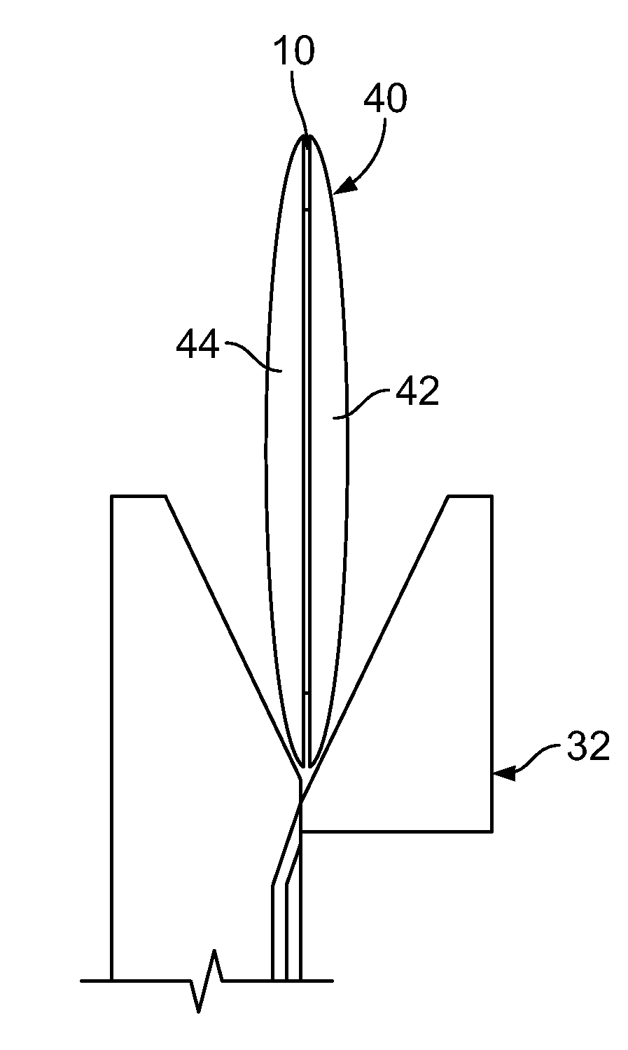
[0057]Pursuant to an aspect of an embodiment of the present invention, because of the industry standard data-reduction algorithms used and because the ultimate application of the materials of interest involve their interactions with plane electromagnetic waves, it is desirable to create a close approximation to a plane wave environment at a sample under test. Further, it is also generally desirable to limit the size of the sample required for testing to le...


PUM


Abstract

A plane wave antenna including: a horn antenna; a waveguide at least partially inside the horn antenna, wherein the waveguide includes: a central dielectric slab increasing in width toward the horn antenna and with a first dielectric constant, an upper slab above the central dielectric slab with a second dielectric constant, and a lower slab below the central dielectric slab with the second dielectric constant; wherein the central dielectric slab has a substantially constant thickness less than a quarter of a wavelength at a highest frequency of operation of the plane wave antenna.

Description

CROSS-REFERENCE TO RELATED APPLICATION[0001]This application claims priority to and the benefit of U.S. Provisional Application No. 60 / 871,551 filed Dec. 22, 2006, the entire contents of which are expressly incorporated herein by reference.FIELD[0002]Broadband antennas or admittance tunnel incorporating the same are generally discussed herein, with particular discussions extended to a compact broadband antenna with a polyrod and / or an admittance tunnel incorporating a broadband antenna and an iris.BACKGROUND[0003]An admittance tunnel is generally defined as a test set-up for measuring the constitutive parameters of dielectric and magneto-dielectric materials in a plane-wave environment. One of its principal uses is to characterize lossy materials for absorption of electromagnetic energy, which may have attenuation constants in the range of 0.1 dB / inch to 40 dB / inch and relative permittivities in the range from 1.01 to 40. Man-made lossy materials manufactured in bulk quantities may ...

Claims


Application Information

Patent Timeline
Patent Type & Authority Patents(United States)
IPC IPC(8): H01Q13/00
CPCH01Q13/0275H01Q13/24
Inventor DIAZ, RODOLFOPEEBLES, JEFFREYLEBARON, RICHARDZHANG, ZHICHAOLOZANO-PLATA, LORENA
Owner ARIZONA STATE UNIVERSITY
Why Eureka
Try Eureka