Central body of a turbojet nozzle

a technology of central body and turbojet nozzle, which is applied in the direction of machines/engines, climate sustainability, sustainable transportation, etc., can solve the problems of difficult installation, high price and weight, and difficult to fold metal sheets into honeycombs, etc., and achieve the effect of improving mechanical strength

Active Publication Date: 2011-02-22
SN DETUDE & DE CONSTR DE MOTEURS DAVIATION S N E C M A
View PDF17 Cites 15 Cited by
  • Summary
  • Abstract
  • Description
  • Claims
  • Application Information

AI Technical Summary

Benefits of technology

[0011]Such a central body makes it possible to attenuate low frequency noises. It forms a Helmholtz resonator with a plurality of orifices and a single cavity common to all the orifices. The invention therefore has consisted in replacing a central body, with a plurality of cavities forming Helmholtz resonators, with a central body with a single cavity, common to a plurality of orifices, forming a single Helmholtz resonator. Although the acoustic performance of such a resonator is worse than that of the devices of the prior art explained hereinabove—it is possible to predict a 30% reduction in attenuation performance—, the cost and weight of such a central body are markedly reduced. The invention therefore resides in a device offering a compromise between the acoustic attenuation performance on the one hand, and the cost and weight of the acoustic attenuation device on the other hand. The longitudinal extent of the upstream portion pierced with orifices is preferably determined by computations, based on a law of static pressure within the cavity, the downstream limit of this portion being fixed according to maximum tolerated aerodynamic losses, by recirculation of the exhaust gas stream in the cavity. Note that, if high losses are tolerated, the upstream wall may mean the whole wall of the central body.
[0013]Such a wall makes it possible to regulate the volume of the resonator and hence to adapt it to the frequencies that it is desired to attenuate. Furthermore, this wall may, where necessary, in the case of a turbojet comprising a deaerator, make it possible to separate the cavity of the central body into two cavities: a resonance cavity and a cavity for guidance of the vapor relief stream.
[0017]Advantageously again, the central body comprises at least one stiffener means making it possible to improve its mechanical strength.

Problems solved by technology

They are however very costly, in price and in weight, to install.
It is almost impossible—and therefore expensive—to fold metal sheets formed into honeycombs, while installing larger cavities is awkward and of some weight.

Method used


Image

  • Central body of a turbojet nozzle
  • Central body of a turbojet nozzle

Examples


second embodiment

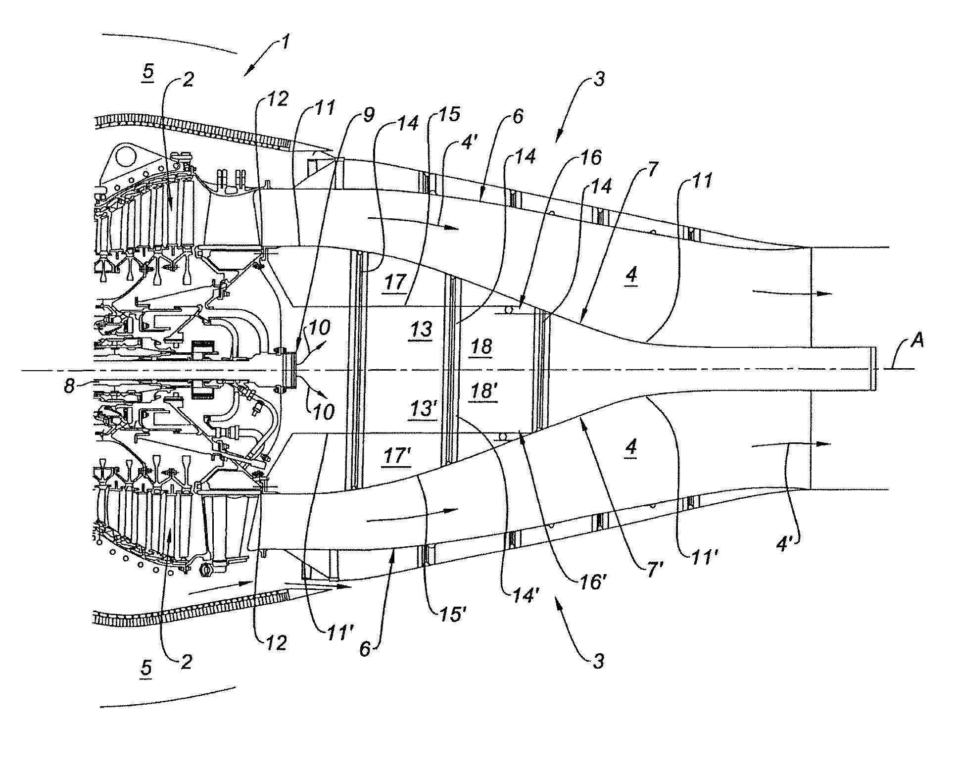
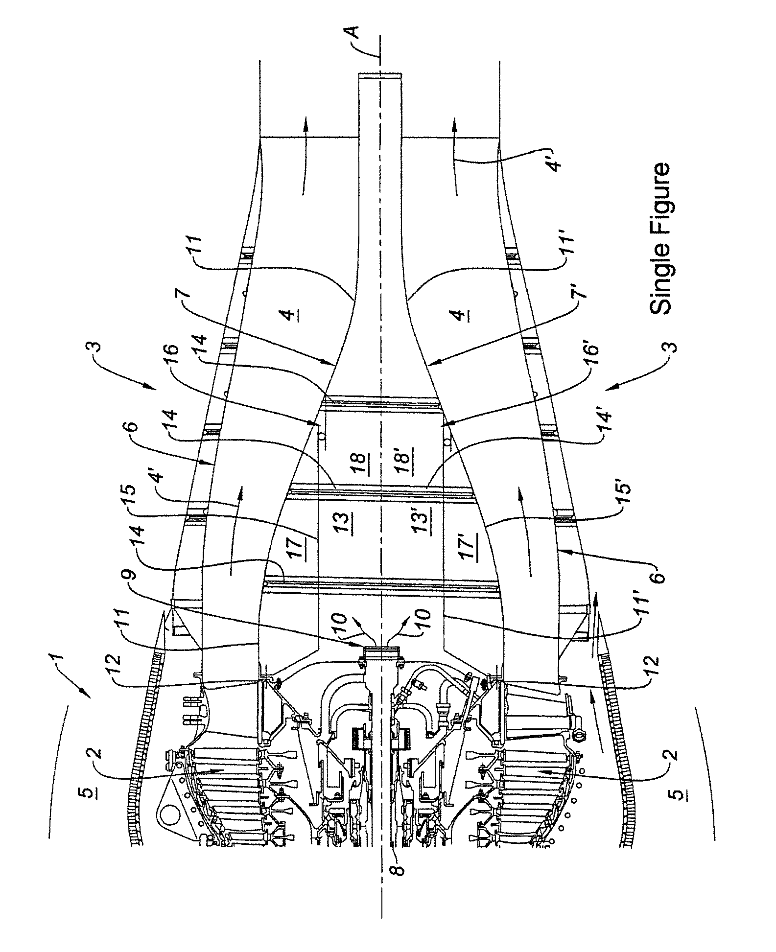
[0038]In this second embodiment, the wall of revolution defining the global cavity 13′ of the central body therefore consists of the outer wall 15′ and a downstream portion of the single-piece wall 11′, the upstream portion of which defines the inner wall of the resonance cavity 17′. There is however again a global cavity 13′ of the central body 7′, a single resonance cavity 17′, in communication with the orifices opening into the primary gas stream, and an inner cavity for the guidance of the vapor relief stream originating from the deaerator 9, not communicating with the resonance cavity 17′.

first embodiment

[0039]As above, the walls 11′, 15′ forming the resonance cavity 17′ are connected by a seal 16′, in order to take up the expansion differentials, and stiffener means 14′, in the form of ribs, are provided for the mechanical strength of the central body 7′. It is the fitted outer wall 15′ that comprises the orifices, opening into the primary gas stream and communicating with the resonance cavity 17′ to form a Helmholtz resonator with a single resonance cavity 17′, common to the orifices. The various comments made for the first embodiment apply mutatis mutandis.

[0040]It goes without saying that the structure and the arrangement of the various embodiments may be modified by those skilled in the art.

[0041]In particular, in the absence of a deaerator 9, those skilled in the art may decide not to provide an inner wall 15 within the global cavity 13 of the central body 7. In this case, it is the whole of the cavity 13 formed by the wall of revolution 11 that forms a resonance cavity 13, in...


PUM


Abstract

A device for attenuating acoustical noise from an exhaust nozzle of a turbojet is disclosed. The turbojet exhaust nozzle includes a central body defining the inner surface of the primary gas flow path. The central body includes an outer wall defining one, and only one, resonator cavity. The single resonator cavity is in fluid communication with the primary gas flow path via orifices through at least one upstream portion of the outer wall. The single resonator cavity and plurality of orifices compose a Helmholtz resonator.

Description

[0001]The invention relates to the field of noise reduction at the outlet of a turbojet.BACKGROUND OF THE INVENTION[0002]A turbojet comprises, from upstream to downstream in the direction of the gas flow, a fan, one or more compressor stages, a combustion chamber, one or more turbine stages and a gas exhaust nozzle. These are the gases of the primary stream of the turbojet, that is to say the gas stream at the outlet from the turbine stages and originating from the combustion chamber that escape via the gas exhaust nozzle.[0003]The nozzle usually comprises an outer nozzle casing that delimits the outer envelope of the gas jet of the exhaust stream, as well as an inner nozzle casing that delimits the inner envelope of the gas jet of the exhaust stream to help with its flow. The inner nozzle casing forms a central body of the nozzle and has the shape of a wall having a surface of revolution, that may be cylindrical, conical or more usually of an aerodynamic shape adapted to the stream...

Claims


Application Information

Patent Timeline
Patent Type & Authority Patents(United States)
IPC IPC(8): F02K1/00
CPCF02K1/827F05D2260/96Y02T50/671Y02T50/60
Inventor BOUTY, ERIC JEAN-LOUISDRAVET, ALAINLE DOCTE, THIERRY JACQUES ALBERTRIOU, GEORGES JEAN XAVIERVINCENT, THOMAS ALAIN CHRISTIAN
Owner SN DETUDE & DE CONSTR DE MOTEURS DAVIATION S N E C M A
Why Eureka
Try Eureka