Solid laser apparatus

a laser and laser technology, applied in the direction of lasers, semiconductor lasers, optical resonator shapes and construction, etc., can solve the problems of optical noise generation, and achieve the effect of reducing noise, reducing noise, and effectively attenuating nois

Inactive Publication Date: 2006-08-03
SHIMADZU CORP
View PDF3 Cites 0 Cited by
  • Summary
  • Abstract
  • Description
  • Claims
  • Application Information

AI Technical Summary

Benefits of technology

[0042] As set forth above, the solid laser apparatus according to the present invention has either the combination of the lowpass filter and the highpass filter or the bandpass filter provided in the output control circuit for increasing the gain in the vicinity of the relaxation oscillating frequency and carrying out the phase controlling action in the vicinity of the relaxation oscillating frequency. Since the gain becomes low throughout the range of frequencies other than the relaxation oscillating frequency, any external interruption (e.g. circuitry noise) can effectively be rejected thus effecting the attenuation of optical noise.
[0043] Also, the solid laser apparatus according to the present invention has the phase shift circuit provided in its output control circuit for advancing the phase of a signal in the vicinity of the relaxation oscillating frequency thereof.
[0044] This allows the phase shift action of the phase shift circuit to be operative, thus effecting the attenuation of the optical noise through the feedback controlling action of the output control circuit.
[0045] Moerover, the solid laser apparatus according to the present invention has a pseudo notch filter, which is arranged for the gain to have a local minimum at the relaxation oscillating frequency of the solid laser apparatus, provided in the output control circuit so that the peak of the gain transmission characteristic of the nonlinear optical device or of a combination of the nonlinear optical device and the microchip laser crystal is offset, hence effecting the attenuation of optical noise in the vicinity of the relaxation oscillating frequency. Since the phase transmission characteristic of the pseudo notch filter is inverted in the vicinity of the relaxation oscillating frequency, its action in combination with the phase transmission characteristic of the nonlinear optical device or of the nonlinear optical device and the microchip laser crystal, which provides inversion of the phase in the vicinity of the relaxation oscillating frequency, permits the phase to remain not inverted in the vicinity of the relaxation oscillating frequency. Accordingly, both low frequency noise and high frequency noise can effectively be attenuated by the feedback controlling action of the output control circuit.

Problems solved by technology

Such an optical noise may be generated in the vicinity of the relaxation oscillating frequency fk and remain delayed by substantially 90 degrees in the phase.

Method used


Image

  • Solid laser apparatus
  • Solid laser apparatus
  • Solid laser apparatus

Examples


first embodiment

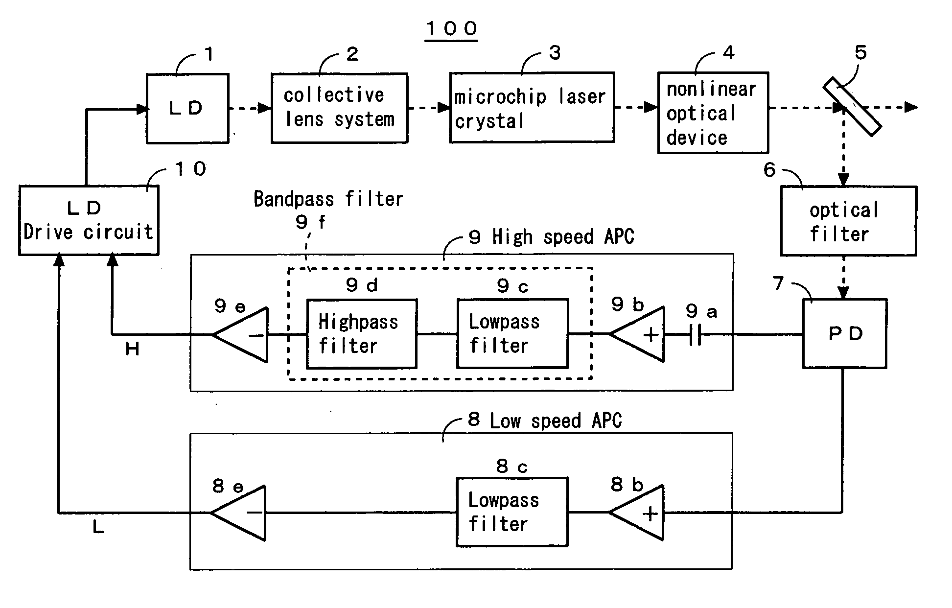
[0071]FIG. 1 is a schematic diagram of a solid laser apparatus 100 showing the first embodiment of the present invention.

[0072] The solid laser apparatus 100 comprises a semiconductor laser 1 for generating a laser beam, a collective lens system 2 for focusing the laser beam, a microchip laser crystal 3 provided with its crystal end faces coated for use as an optical resonator which can be excited by the focused laser beam, a nonlinear optical device 4 for receiving the laser beam from the microchip laser crystal 3 and emitting its harmonic light, an assembly of a splitter 5, an optical filter 6, and a photo diode 7 for detecting the intensity of the light emitted from the nonlinear optical device 4, a low speed APC (automatic power control) circuit 8 for releasing a control signal L to set the intensity of the beam detected by the photo diode 7 to a predetermined level, a high speed APC circuit 9 for releasing a control signal H to attenuate noise components in the beam detected b...

second embodiment

[0090]FIG. 11 is a schematic view of a solid laser apparatus 200 showing the second embodiment of the present invention.

[0091] The solid laser apparatus 200 is identical in the construction to the solid laser apparatus 100 of the first embodiment, except that the microchip laser crystal 3 is eliminated.

[0092] The solid laser apparatus 200 provides the same advantages as the solid laser apparatus 100 of the first embodiment. More specifically, the combination of a lowpass filter 9c and a highpass filter 9d can allow any optical noise to be effectively attenuated through the feedback controlling action of a high speed APC circuit 9.

third embodiment

[0093]FIG. 12 is a schematic diagram of a solid laser apparatus 300 showing the third embodiment of the present invention.

[0094] The solid laser apparatus 300 comprises a semiconductor laser 1 for generating a laser beam, a collective lens system 2 for focusing the laser beam, a microchip laser crystal 3 provided with its crystal end faces coated for use as an optical resonator which can be excited by the focused laser beam, a nonlinear optical device 4 for receiving the laser beam from the microchip laser crystal 3 and emitting its harmonic light, an assembly of a splitter 5, an optical filter 6, and a photo diode 7 for detecting the intensity of the light emitted from the nonlinear optical device 4, a low speed APC (automatic power control) circuit 8 for releasing a control signal L to set the intensity of the beam detected by the photo diode 7 to a predetermined level, a high speed APC circuit 9 for releasing a control signal H to attenuate noise components in the beam detected ...


PUM


Abstract

A solid laser apparatus has either a combination of a lowpass filter (9c) and a highpass filter (9d) or a bandpass filter 9f provided in its output control circuit (8, 9, 10) for increasing the gain and adjusting the phase of a signal in the vicinity of the relaxation oscillating frequency.
Also, a solid laser apparatus has the phase shift circuit (9g) provided in its output control circuit (8,9,10) for advancing the phase of a signal in the vicinity of the relaxation oscillating frequency thereof.
Moreover, a solid laser apparatus has a pseudo notch filter (9h), which is arranged for the gain to have a local minimum at the relaxation oscillating frequency of the solid laser apparatus, provided in the output control circuit (8,9,10) so that the peak of the gain transmission characteristic of the nonlinear optical device (4) or of a combination of the nonlinear optical device (4) and the microchip laser crystal (3) is offset.

Description

FIELD OF THE INVENTION [0001] The present invention relates to a solid laser apparatus and more particularly to a solid laser apparatus which can effectively attenuate optical noises. BACKGROUND OF THE INVENTION [0002] A solid laser apparatus is known comprising a semiconductor laser for generating a laser beam, a nonlinear optical device for receiving the laser beam from the semiconductor laser and emitting its harmonic light, an optical detecting means used as a monitor for detecting the intensity of the light emitted from the nonlinear optical device, and an output control circuit for driving the semiconductor laser so as to maintain the intensity of the light at a predetermined level (See Citation 1). [0003] Another solid laser apparatus is known having a microchip laser crystal designed for being excited by the laser beam emitted from a semiconductor laser, provided with its crystal end faces coated for use as an optical resonator, and located at the upstream of an nonlinear op...

Claims


Application Information

Patent Timeline
Patent Type & Authority Applications(United States)
IPC IPC(8): H01S5/00H01S3/06H01S3/08H01S3/0941H01S3/10H01S3/109H01S3/13H01S3/131H01S5/06H01S5/062H01S5/068
CPCH01S3/005H01S3/0092H01S3/0627H01S3/0941H01S3/1305H01S3/1312H01S5/06223H01S5/068H01S5/06817H01S2301/02H01S2301/04
Inventor TOJO, KOJIIRIKUCHI, SATOSHIWATANABE, KAZUMASUGIMOTO, TUNEHIROFUKUSHI, ICHIROISHIGAKI, NAOYAINOUE, KOJI
Owner SHIMADZU CORP
Why Eureka
Try Eureka