Optical head apparatus, optical disk apparatus and optical disk

a head apparatus and optical disk technology, applied in the field of optical head apparatuses, can solve the problems of large playback energy needed in comparison to that of a conventional optical disk, and achieve the effects of accurate data playback, reduced low frequency noise, and reduced variation in playback signal

Inactive Publication Date: 2012-09-18
MITSUBISHI ELECTRIC CORP
View PDF36 Cites 1 Cited by
  • Summary
  • Abstract
  • Description
  • Claims
  • Application Information

AI Technical Summary

Benefits of technology

[0023]The apparatus according to the invention reduces a low frequency noise contained in the playback signals, to reduce a variation in the playback signal, thus achieving an accurate data playback. Further, when there exists a positional displacement between the light receiving surface and the return optical beam, or an asymmetrical intensity distribution of the return optical beam, the low frequency noise can be suppressed, thus allowing a playback characteristic of an optical disk to be stabilized, which provides enhanced reliability.

Problems solved by technology

In such a super resolution optical disk, however, because a mask layer thereof absorbs light, larger playback energy is needed in comparison to that in a conventional optical disk.

Method used


Image

  • Optical head apparatus, optical disk apparatus and optical disk
  • Optical head apparatus, optical disk apparatus and optical disk
  • Optical head apparatus, optical disk apparatus and optical disk

Examples


embodiment 1

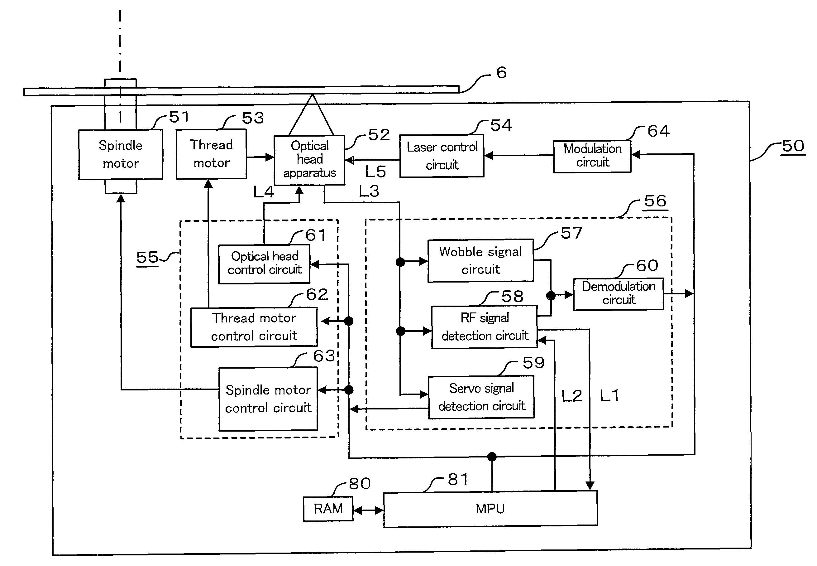
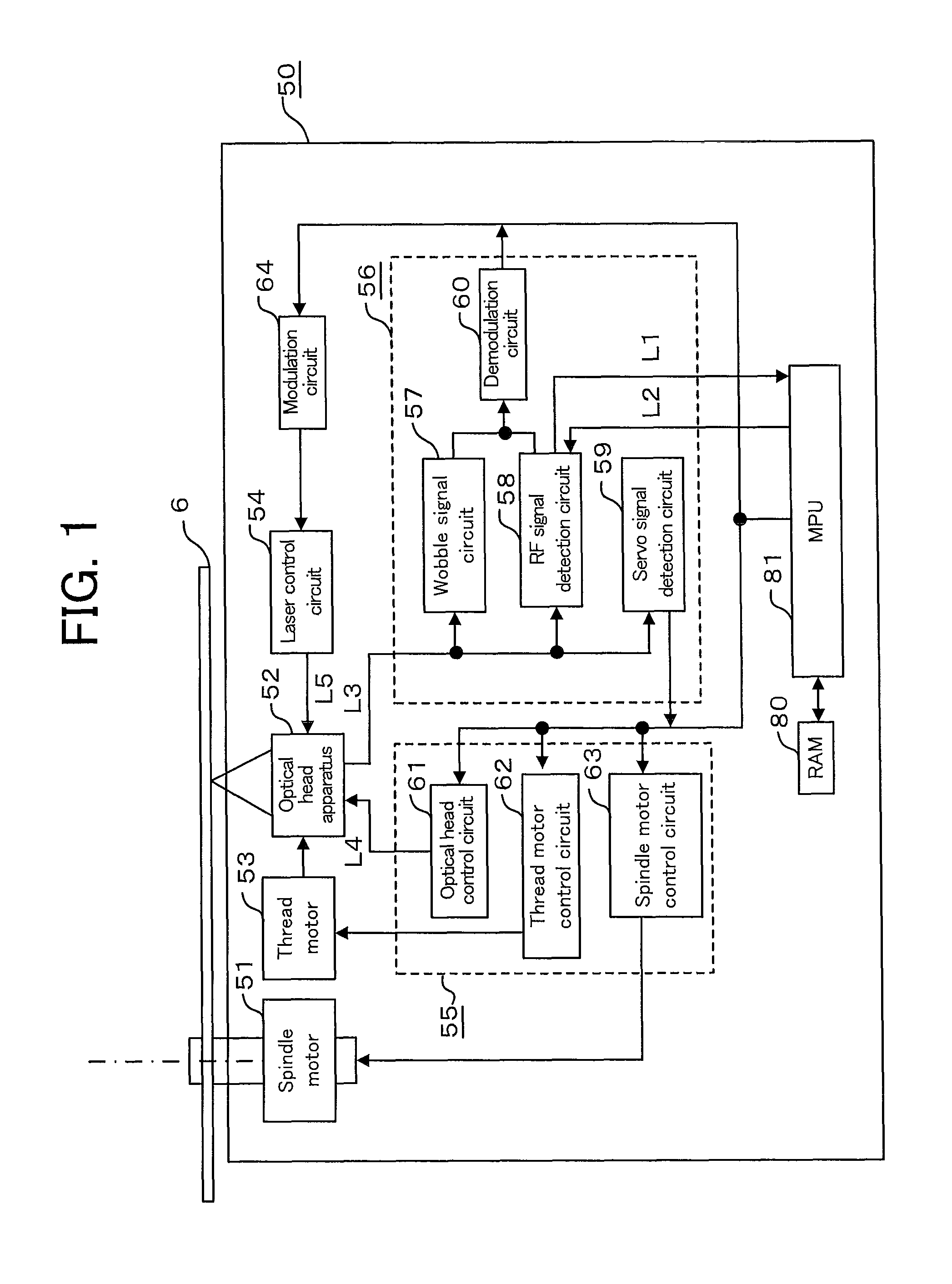
[0063]FIG. 1 is a view illustrating an overall configuration of an optical disk apparatus according to Embodiment 1. Here, arrows in FIG. 1, which indicate flows of typical signals and information, do not represent all connections between blocks constituting an optical disk apparatus 50.

[0064]Referring to FIG. 1, the optical disk apparatus 50 comprises a spindle motor 51 for rotationally driving an optical disk 6, an optical head apparatus 52 that shines a laser beam onto the optical disk 6 and then receives return light reflected by an information recording layer of the optical disk 6, to thereby generate signals, a thread motor 53 for driving the optical head apparatus 52 in a radial direction of the optical disk 6, a laser control circuit 54, a servo control circuit 55, a playback signal processing circuit 56, a modulation circuit 64, a Random Access Memory (RAM) 80, and a Micro Processing Unit (MPU) 81.

[0065]The servo control circuit 55 includes a spindle motor 63 that controls ...

embodiment 2

[0149]Embodiment 2 will be described below with reference to FIGS. 12 through 15.

[0150]An optical head apparatus according to Embodiment 2 is such that in an optical head apparatus that emphasizes the outer portion beam having a higher CN ratio in comparison to the center portion beam of all portions of the return optical beam Q, to detect the outer portion beam, the CN ratio of the playback signal RF is improved which is a combined signal of output signals from a plurality of light receiving elements that detect the center portion beam and the outer portion beam by adjusting amplitude gains of the output signals detected with the light receiving elements.

[0151]FIGS. 12 through 15 are schematic diagrams of the light receiving device 27, showing the light receiving surface 8, the return optical beam Q, and an arithmetic operation circuit for the playback signal RF in the signal arithmetic operation unit 109. The light receiving surface 8 shown here corresponds to various surface patt...

embodiment 3

[0161]Embodiment 3 according to the present invention will be described below with reference to FIGS. 16 through 22.

[0162]FIG. 16 is a diagram showing an overall configuration of an optical disk apparatus according to Embodiment 3.

[0163]The difference from that of FIG. 1 is that a signal on a transmission line L6 from the RF signal detection circuit 58 controls an arithmetic operation circuit of the optical head apparatus 52.

[0164]What FIG. 17 shows is the optical disk apparatus according to the invention, in which only configurations of the light receiving device 27 and the RF signal detection circuit 58 are shown and the optical system from the semiconductor laser down to the light receiving surface is not depicted. The light receiving surface in FIG. 17, which corresponds to the split light receiving element of FIGS. 6 and 12 of Embodiment 1, is applicable to all light receiving surfaces that are described in the present invention.

[0165]The light receiving device 27 includes a li...


PUM

PropertyMeasurementUnit
thicknessaaaaaaaaaa
thicknessaaaaaaaaaa
thicknessaaaaaaaaaa

Abstract

[Object] A recoding playback apparatus and an optical disk are provided that allows reduction of a low frequency noise at a time of playback of a super resolution optical disk including small record marks whose size is below the diffractive limitation, to enhance quality of a playback signal.[Means for Solution] The reflective beams from the optical disk are received by dividing into outer portion beams and a center portion beam, and a playback signal is created by combining such beams based on respective different gains. Based on received amounts of light or amounts of low frequency noise in respective light receiving regions, adjustment or determination of gain values is made, or the optical head apparatus is optically adjusted, whereby the low frequency noise is optimally suppressed. Further, a specific region is provided on the optical disk for making the foregoing adjustment.

Description

TECHNICAL FIELD[0001]The present invention relates to optical head apparatuses, optical disk apparatuses that record information on or play back information from optical recording / playback media for use in a super-resolution system, and optical disks which information is recorded on or played back from using the optical disk apparatus.BACKGROUND ART[0002]Thus far, high-capacity optical disks of various kinds have been achieved by reducing the size of an information mark that is written on a disk track and also by making a wavelength of the laser beam for use in recording / playback shorter and adopting an objective lens of a larger numerical aperture, to reduce the size of a focus spot on a focusing surface.[0003]In, for example, a CD (compact disc), its disk substrate serving as an optical transmissive layer (a transparent protective layer formed on an information recording layer, which is also called a transparent substrate) has a thickness of about 1.2 mm, a laser beam wavelength o...

Claims


Application Information

Patent Timeline
Patent Type & Authority Patents(United States)
IPC IPC(8): G11B7/00G11B7/13
CPCG11B7/005G11B7/00736G11B7/133G11B7/131G11B7/24G11B7/12G11B7/09
Inventor NAKAI, KENYA
Owner MITSUBISHI ELECTRIC CORP
Why Eureka
Try Eureka