Eureka AIR delivers breakthrough ideas for toughest innovation challenges, trusted by R&D personnel around the world.

Motor and compressor with motor

A technology of rotor and magnetic isolation bridge, which is applied in the fields of motors and compressors with the motors, can solve the problem of increasing the amplitude of the magnetic density fundamental wave in the no-load air gap, unfavorable for the realization of the automatic winding process of the stator, and unfavorable production line air gaps. Process inspection and other issues to achieve the effect of reducing low-frequency radial electromagnetic force, simple structure and reliable performance

Inactive Publication Date: 2014-01-15
GUANGDONG MEIZHI PRECISION MFG
View PDF7 Cites 12 Cited by
  • Summary
  • Abstract
  • Description
  • Claims
  • Application Information

AI Technical Summary

Problems solved by technology

For example, reducing the width of the slot of the stator core to reduce the harmonics of the stator teeth, but this method is not conducive to the realization of the stator automatic winding process; using the method of uneven air gap to optimize the air gap magnetic field, but increasing Larger tooth harmonics will also cause losses to the fundamental magnetic flux density, and are not conducive to the air gap process inspection of the production line; the use of inclined slots or inclined poles not only weakens the fundamental magnetic flux density, but also makes it difficult to achieve mass production ;Using a concave structure at the q-axis, this method is not optimized because the air-gap magnetic density is not optimized. When the amplitude of the no-load air-gap magnetic density fundamental wave increases, the higher harmonics also increase, so the noise vibration There may be deterioration, and the iron loss tends to increase; two different stator and rotor punches are used to reduce torque ripple and radial electromagnetic force. This form of configuration is too diverse, and it is not suitable for mass production process is unfavorable

Method used


Image

  • Motor and compressor with motor
  • Motor and compressor with motor
  • Motor and compressor with motor

Examples


Embodiment Construction

[0035] Embodiments of the present invention are described in detail below, examples of which are shown in the drawings, wherein the same or similar reference numerals designate the same or similar elements or elements having the same or similar functions throughout. The embodiments described below by referring to the figures are exemplary only for explaining the present invention and should not be construed as limiting the present invention.

[0036] In describing the present invention, it should be understood that the terms "center", "longitudinal", "transverse", "upper", "lower", "front", "rear", "left", "right", " The orientations or positional relationships indicated by "vertical", "horizontal", "top", "bottom", "inner" and "outer" are based on the orientations or positional relationships shown in the drawings, and are only for the convenience of describing the present invention and Simplified descriptions, rather than indicating or implying that the device or element refe...


PUM


Abstract

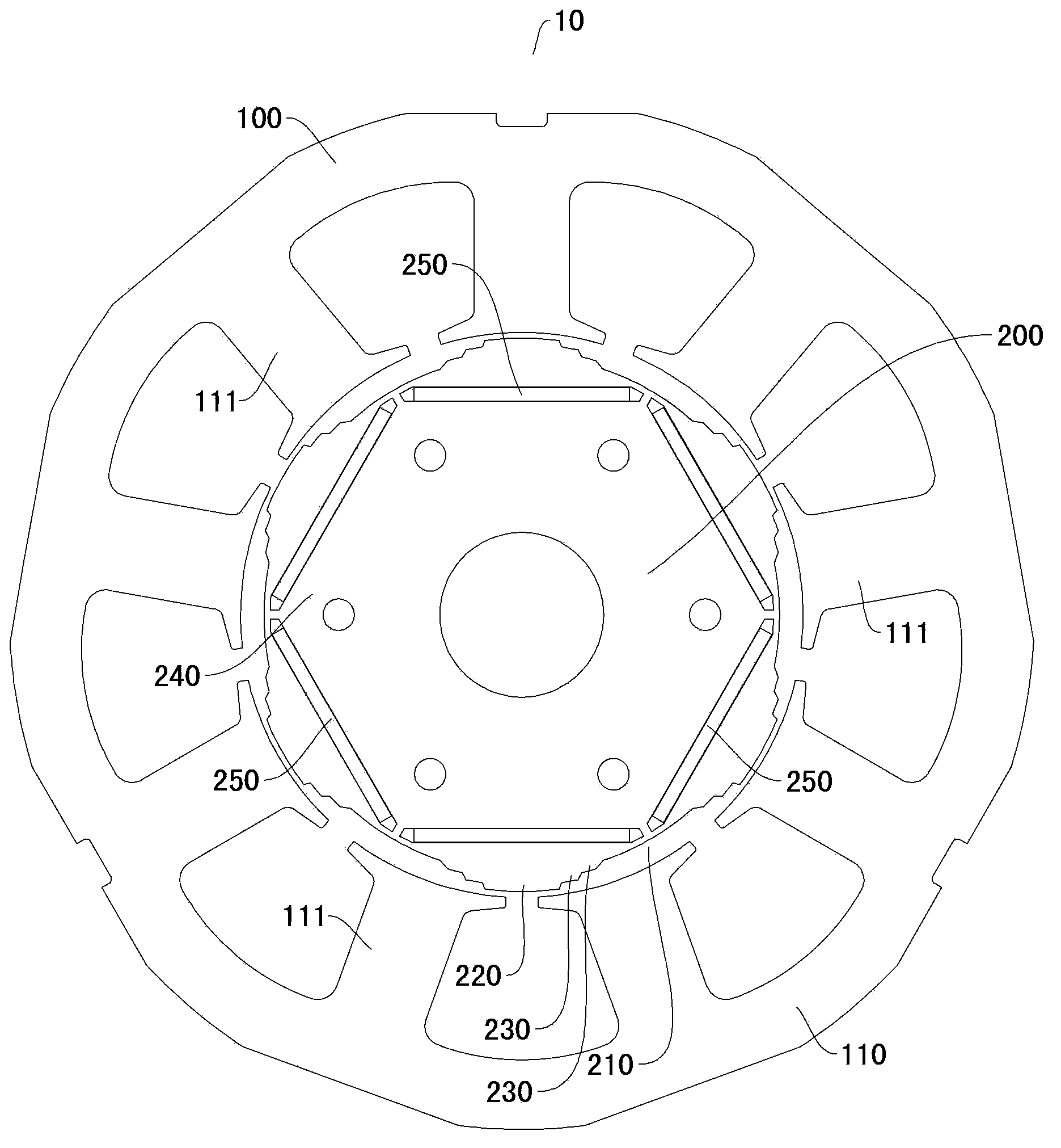
The invention discloses a motor and a compressor with the motor. The motor comprises a stator and a rotor. The rotor is rotatably arranged inside the stator, the outer circumferential surface of the rotor is provided with a plurality of downward concave parts which are arranged at intervals in the circumferential direction of the rotor, protruding parts are formed between every two adjacent downward concave parts, and each protruding part is in transition with the downward concave part adjacent to the protruding part through a step part. According to the embodiment, the motor has the advantages of being low in noise, simple in structure, efficient in performance, easy to manufacture, capable of being produced in batches and the like.

Description

technical field [0001] The invention relates to a driving device, in particular to a motor and a compressor with the motor. Background technique [0002] As one of the main sources of compressor low-frequency noise, the electromagnetic noise of the motor has attracted much attention. The electromagnetic noise of the motor is mainly generated by the radial force wave acting on the stator, and the radial force wave originates from the air gap magnetic field of the motor. The air-gap magnetic field of the existing motor contains a large number of low-order harmonics, and the promotion of these harmonics to the low-frequency radial electromagnetic force is very obvious. [0003] At present, there are many ways to optimize the air gap magnetic field, but all of them have certain defects. For example, reducing the width of the slot of the stator core to reduce the harmonics of the stator teeth, but this method is not conducive to the realization of the stator automatic winding p...

Claims


Application Information

Patent Timeline
Patent Type & Authority Applications(China)
IPC IPC(8): H02K29/03H02K1/24H02K1/27
Inventor 邱小华于明湖
Owner GUANGDONG MEIZHI PRECISION MFG
Why Eureka
Eureka Blog
Learn More