Jumper connector for a lighting assembly

a technology for connecting connectors and lighting components, which is applied in the direction of lighting and heating apparatus, coupling device connections, lighting support devices, etc., can solve the problems of reducing device life, affecting the performance of lighting components, and time-consuming electrical connection of lighting components with wires

Active Publication Date: 2011-02-22
TYCO ELECTRONICS LOGISTICS AG (CH)
View PDF16 Cites 37 Cited by
  • Summary
  • Abstract
  • Description
  • Claims
  • Application Information

AI Technical Summary

Problems solved by technology

One aspect of LED technology that has proven problematic is the efficient management and removal of waste heat.
The waste heat results in degraded performance and reduced device life.
The multiple assembly steps of individually securing the lighting components to the substrate and then electrically connecting the string of lighting components with wires is time consuming.
These substrates often are costly or require complicated multi-step manufacturing processes.

Method used


Image

  • Jumper connector for a lighting assembly
  • Jumper connector for a lighting assembly
  • Jumper connector for a lighting assembly

Examples


Embodiment Construction

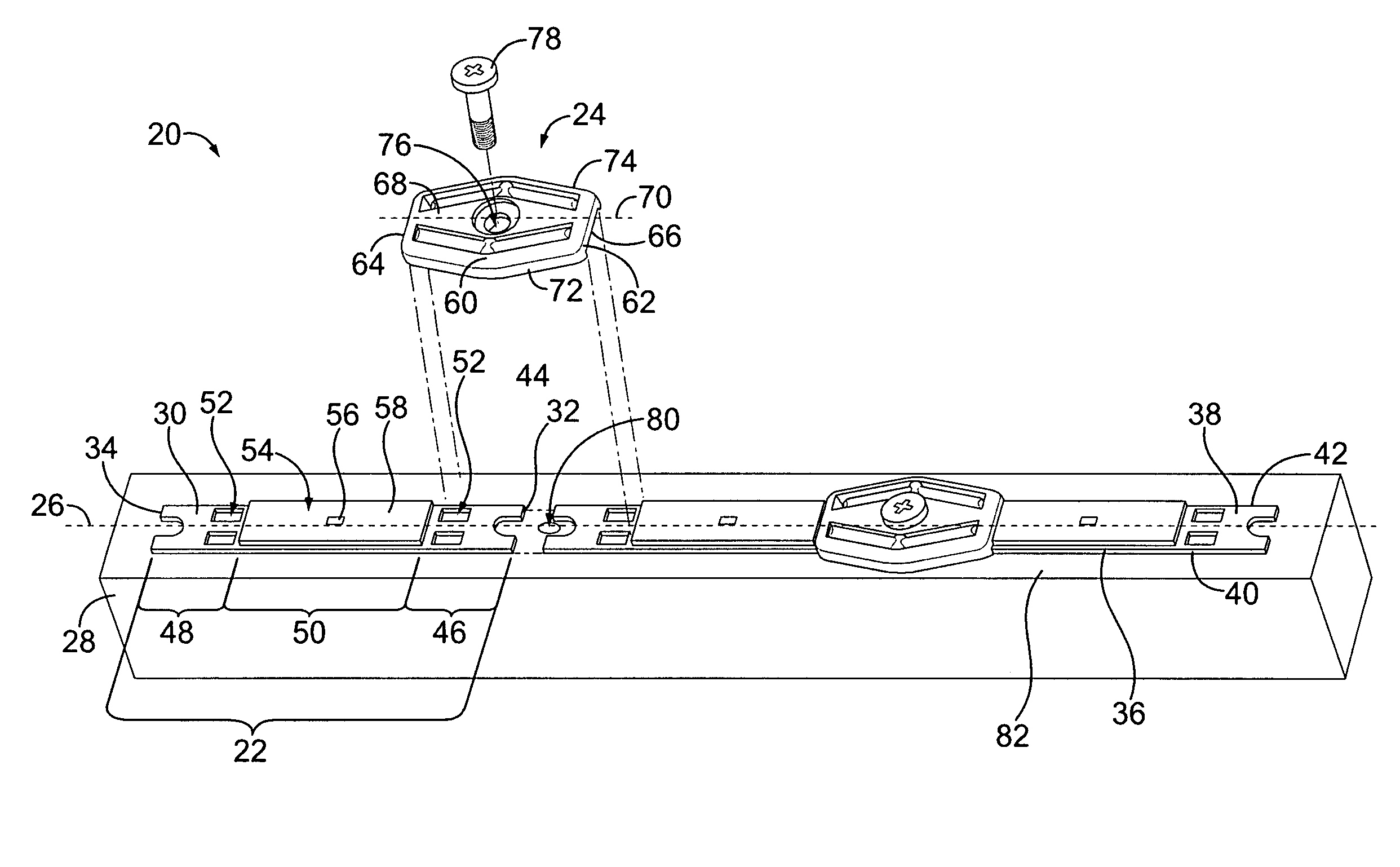
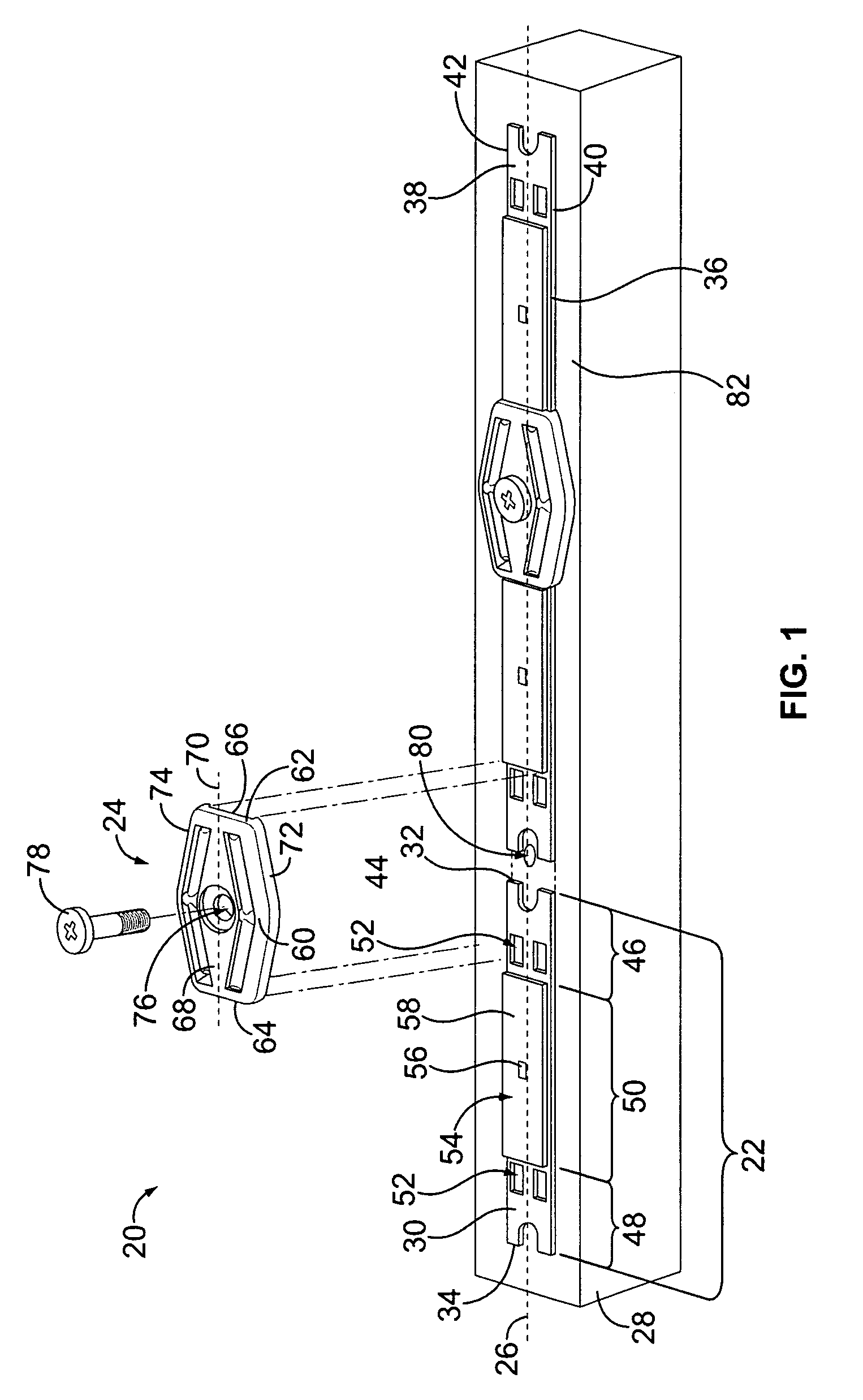
[0022]FIG. 1 illustrates a lighting assembly 20 including multiple lighting components 22 interconnected by jumper connectors 24. The lighting components 22 are arranged in a row along a component axis 26 to form a lighting strip. Any number of lighting components 22 may be used to form the lighting strip. The lighting components 22 are connected in series by the jumper connectors 24, and the jumper connectors 24 form part of an electrical circuit that transmits power between adjacent lighting components 22, as will be described in further detail below.

[0023]The lighting components 22 are secured to a substrate 28. In an exemplary embodiment, the jumper connectors 24 are used to secure the lighting components 22 to the substrate 28. In the illustrated embodiment, the substrate 28 constitutes a heat sink, and may be referred to hereinafter as heat sink 28. The heat sink 28 dissipates heat generated by the lighting components 22 during operation.

[0024]In exemplary embodiment, the ligh...


PUM


Abstract

A jumper connector for connecting lighting components to one another includes a connector body having a mating surface configured to engage more than one lighting component, where the connector body is configured to be secured to a substrate by a fastener. The jumper connector also includes a conductor held by the body, wherein the conductor is configured to be electrically connected to more than one lighting component during the same manufacturing step in which the connector body is secured to the substrate.

Description

BACKGROUND OF THE INVENTION[0001]The subject matter herein relates generally to lighting assemblies, and more particularly, to jumper connectors for lighting assemblies.[0002]Light-emitting diodes (“LEDs”) are now widely applied in a variety of lighting applications. The relatively high efficacy of LEDs (in lumens per watt) is the primary reason for their popularity. Power savings are possible when LED's are used to replace traditional incandescent lighting. One aspect of LED technology that has proven problematic is the efficient management and removal of waste heat. The waste heat results in degraded performance and reduced device life. Typically, to remove waste heat, a heat sink or other heat dissipating device is utilized.[0003]An example of lighting components in use today that utilizes LEDs is the CL-L102 Series of lighting components, commercially available from Citizen Electronics Co. Such lighting components include an elongated circuit board having one or more LED's mount...

Claims


Application Information

Patent Timeline
Patent Type & Authority Patents(United States)
IPC IPC(8): H01R31/08
CPCF21V19/0055F21V21/005F21V23/06F21S4/28F21V29/70H01R25/162H01R31/085H01R12/714H01R33/06F21Y2103/10F21Y2115/10
Inventor MOSTOLLER, MATTHEW EDWARDGINGRICH, III, CHARLES RAYMONDEPPLEY, NAZARETH WAYNE
Owner TYCO ELECTRONICS LOGISTICS AG (CH)
Why Eureka
Try Eureka