Arrangement and method for visual detection in a milking system

a technology of visual detection and milking system, which is applied in the direction of milking devices, manipulators, catheters, etc., can solve the problems of not working satisfactorily, sensor costs may not be negligible, and sensor work may not be reliably or even damaged, so as to achieve low cost or flexible implementation.

Active Publication Date: 2011-03-01
DELAVAL HLDG AB
View PDF26 Cites 29 Cited by
  • Summary
  • Abstract
  • Description
  • Claims
  • Application Information

AI Technical Summary

Benefits of technology

[0011]It is in this respect a particular object of the invention to provide such an arrangement and such a method, which is capable of fastly moving the robot arm to an approximate position of the teats of the milking animal when being in the milking box.
[0013]It is yet a further object of the invention to provide such an arrangement and such a method, which are robust, effective, fast, precise, accurate, reliable, safe, easy to use, and of low cost.
[0014]It is still a further object of the invention to provide such an arrangement and such a method, which are capable of obtaining a very high number of correct teat cup attachments.
[0018]The second visual detection device is provided for detecting a position of the milking animal in a longitudinal direction when being located in the milking box, and the control device is, in an initial phase of the application of the teat cup to the teat of the milking animal, provided for controlling the movement of the robot arm based on the information of the position of the teat of the milking animal relative the milking animal itself, and on the detected position of the milking animal in the longitudinal direction. Hereby, the approximate position of the teat is fastly achieved, and the robot arm can move directly to such position. Then, the control device controls the fine movement of the robot arm based on the repeatedly determined position of the teat of the milking animal relative the robot arm as measured by the first visual detection device mounted on the robot arm.
[0019]The second visual detection device is preferably a two-dimensional camera which covers a larger detection area than the first visual detection device, and has a lower, or much lower, detection frequency than the first visual detection device. For instance, a repetition rate of one image per second would be sufficient for the above purpose. This gives good possibilities for obtaining a cheap and flexible implementation.

Problems solved by technology

A problem with the milking system, wherein a sensor senses the position of a rear plate as displaced by the back of a milking animal while standing in a milking box, is that the sensor is exposed to dirt and possibly physical contact with the milking animal, and as a consequence the sensor may not work reliably or may even be damaged.
Further, the sensor has to be provided for the single purpose of measuring the longitudinal position of the milking animal, and the costs for the sensor may not be negligible.
A problem with the approaches for automatically teaching the milking system where to approximately find the teats of the milking animal is that they may not work satisfactorily, i.e. the number of correct teat cup attachments may be low.
A problem with the approach described in U.S. Pat. No. 4,867,103 is that the milking process may be prolonged if the approximate position of the teats has to be determined for each milking.

Method used


Image

  • Arrangement and method for visual detection in a milking system
  • Arrangement and method for visual detection in a milking system
  • Arrangement and method for visual detection in a milking system

Examples


Embodiment Construction

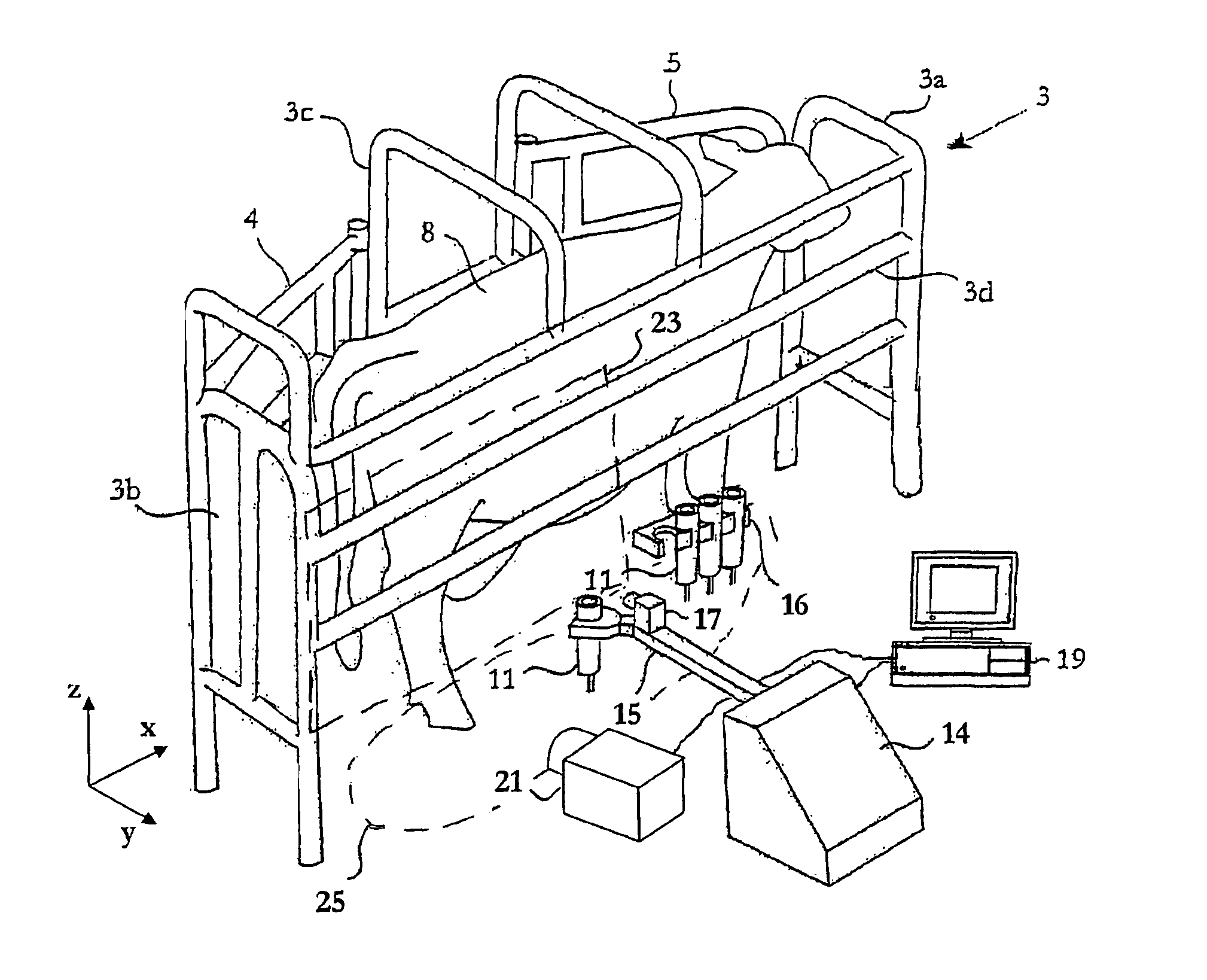
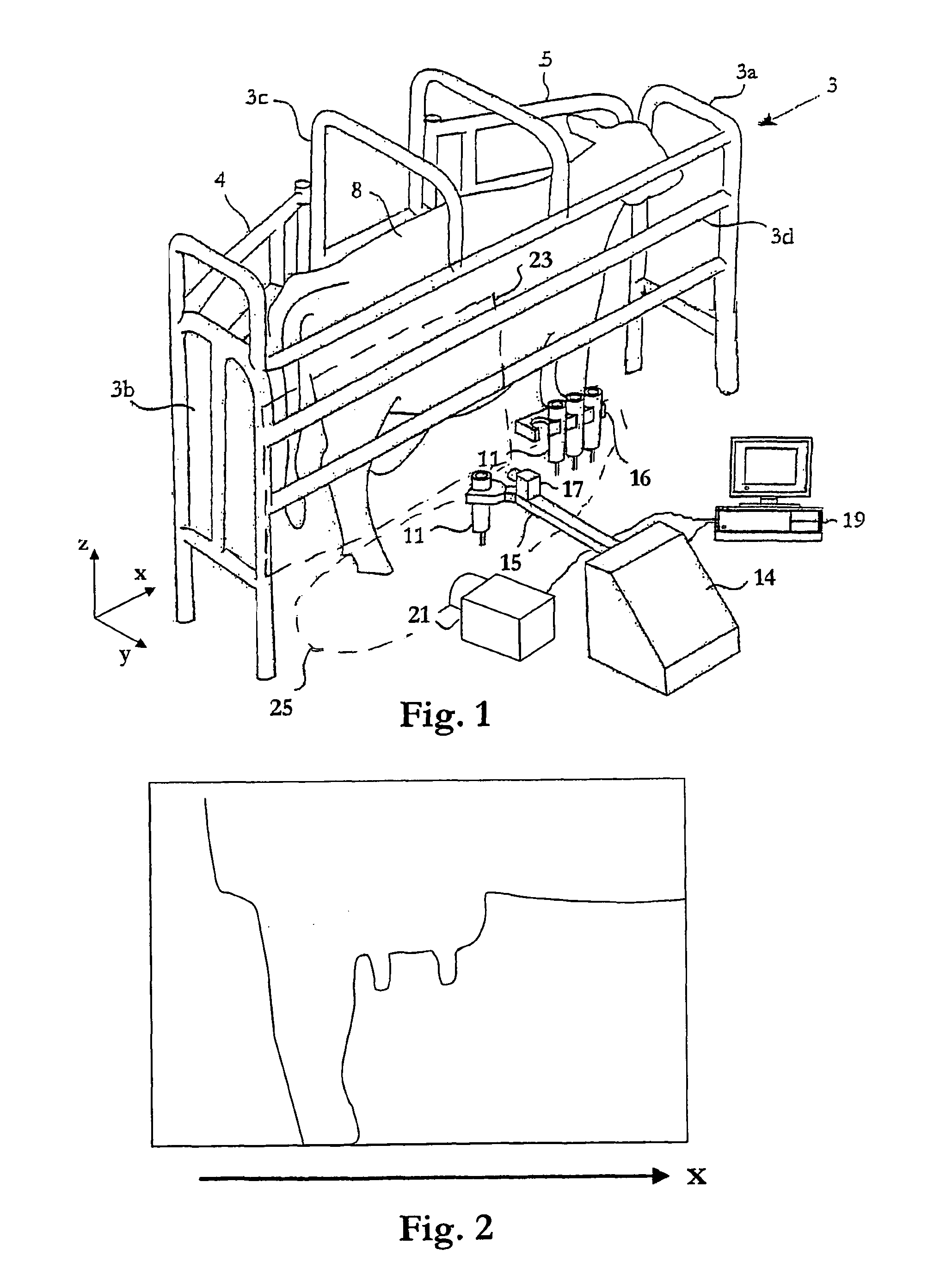
[0031]In FIG. 1 is shown a milking system or station 3 arranged for voluntary milking of freely walking animals such as cows, i.e. the cows enter the milking system 3 in order to be milked on a voluntary basis. The milking system 3 comprises a milking box having an inlet gate 4 and an outlet gate 5, which are both capable of being opened automatically. The front end of the milking box of the milking system 3 is denoted by 3a, the back end is denoted by 3b, the left side is denoted by 3c and the right side is denoted by 3d.

[0032]The milking system 3 comprises further an automatic milking machine (not explicitly illustrated) including teat cups 11 connected to an end unit by means of milk lines (only the portions attached to the teat cups 11 are shown in FIG. 1). The milking system further comprises a milking robot or automatic handling device 14 including a processing and control device 19 and a robot arm 15 provided with a gripper. The milking robot 14 is arranged to automatically ...


PUM


Abstract

A visual detection arrangement is provided in a milking system (3) comprising a robot arm (15) for attaching a teat cup (11) to a teat of a milking animal (8), and a control device (19) for controlling the movement of the robot arm. The detection arrangement comprises first visual detection means (17) provided on the robot arm for repeatedly determining the teat position relative the robot arm and second visual detection means (21) directed towards the milking animal. The second visual detection means (21) is provided for detecting a position of the animal in a longitudinal direction (x), and the control device (19) is initially provided for controlling the movement of the robot arm based on information of the position of the teat of the animal relative the animal itself, and on the detected longitudinal position of the animal.

Description

TECHNICAL FIELD OF THE INVENTION[0001]The present invention generally relates to dairy farm robot milking and to visual detection related thereto.DESCRIPTION OF RELATED ART AND BACKGROUND OF THE INVENTION[0002]In a known milking system, wherein teat cups are automatically attached to the teats of a milking animal to be milked, a robot arm with a gripper is provided to grip and hold teat cups during the attachment of the teat cups. A laser emitting laser light and a video camera provided to register laser light as reflected from the teats of the milking animal are mounted on the robot arm. By aid of a method known as laser triangulation, the positions of the teats can be calculated. The movement of the robot arm can then be controlled in response to the calculated positions to be capable of finding the teats for the teat cup attachments.[0003]In order to operate satisfactorily, the robot arm needs to be close to the teats. Since each milking animal has a different constitution (the u...

Claims


Application Information

Patent Timeline
Patent Type & Authority Patents(United States)
IPC IPC(8): A01J5/00
CPCB25J11/00A01J5/0175
Inventor GUDMUNDSSON, MATSAMOLIN, RAFAELS
Owner DELAVAL HLDG AB
Why Eureka
Try Eureka