Portable shelter structure

a shelter structure and portable technology, applied in the field of portable shelter structures, can solve the problems of perceived drawbacks in each of the foregoing constructions, and achieve the effects of convenient transportation and assembly, convenient use and manufacture, and quick assembly and disassembly

Active Publication Date: 2011-03-01
SHELTERLOGIC
View PDF17 Cites 16 Cited by
  • Summary
  • Abstract
  • Description
  • Claims
  • Application Information

AI Technical Summary

Benefits of technology

[0006]It is yet another objective of the present invention to provide an improved portable shelter structure that allows for relatively quick assembly and disassembly, while at the same time, achieving the other objectives set forth herein.
[0007]Yet another objective of the present invention is to provide an improved portable shelter structure that is both easy to utilize and manufacture and also that achieves all of the advantages and objectives set forth herein.
[0008]For example, it is an objective of the present invention to provide an improved portable shelter structure that can be both transported and assembled easily in view of the construction of the canopy supporting assembly, which comprises one or more pole and / or pole assemblies.
[0009]Yet another objective of the present invention to provide an improved portable shelter structure that has improved vertical adjustability and canopy features.
[0010]Still another objective of the present invention is to provide a portable shelter structure that provides for an improved canopy construction which permits an easier shelter construction as well as an improved design to receive and secure the poles therein.
[0011]And yet another objective of the present invention is to provide an improved portable shelter structure that achieves the objective of providing an adjustable amount of shelter (e.g. cover) next to or otherwise proximate the structure to / on which it is mounted or (e.g.) coupled. For example, the present invention is constructed so as to provide adjustability of positioning of the canopy to extend over / next to the structure itself, thereby providing shelter for a baby carriage and / or food items, just to name a few examples that may be positioned next to the structure.

Problems solved by technology

However, each of the foregoing constructions have what are perceived as drawbacks.

Method used


Image

  • Portable shelter structure
  • Portable shelter structure
  • Portable shelter structure

Examples


Embodiment Construction

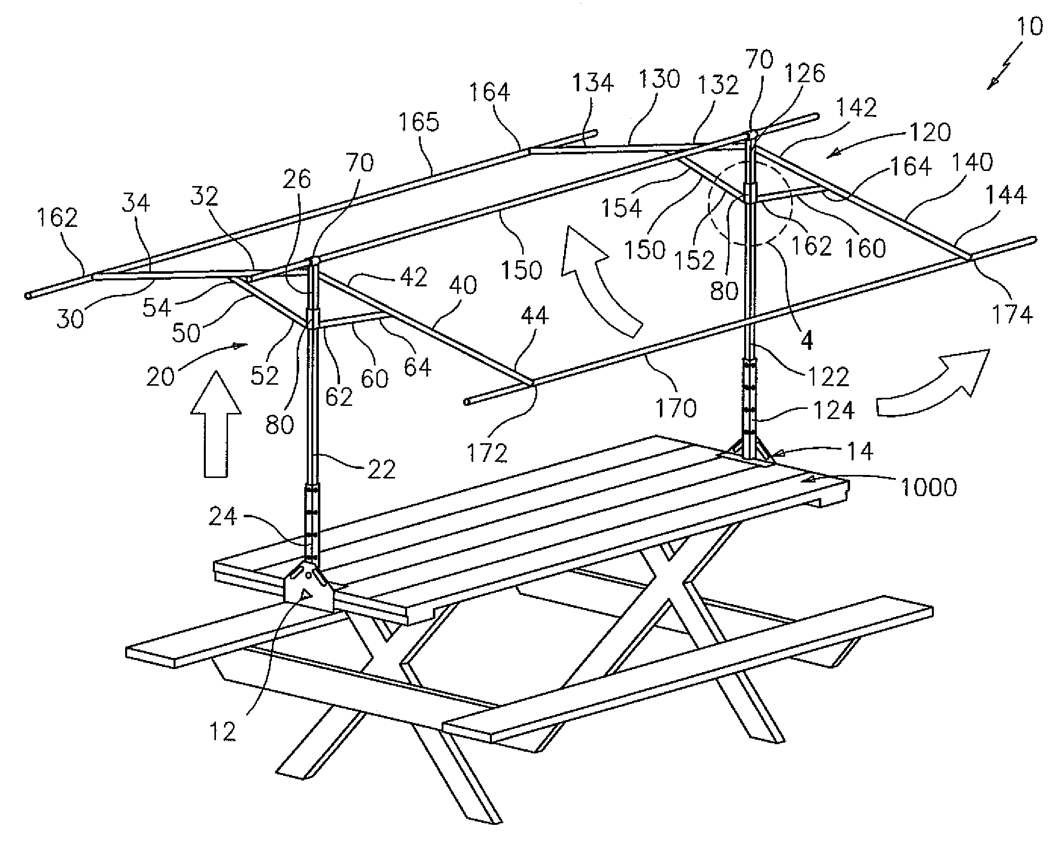
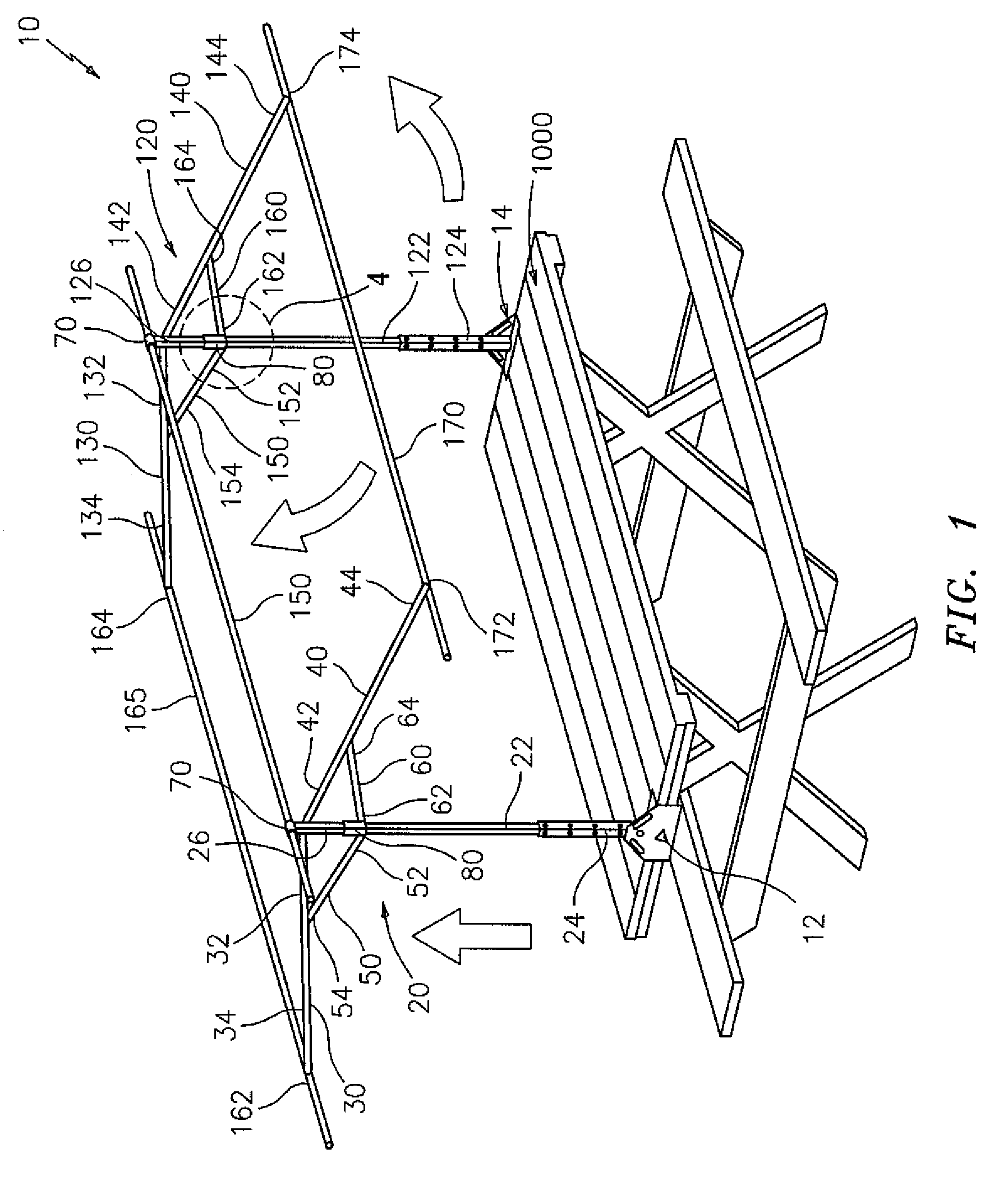
[0025]Reference is made to FIG. 1, which shows a portable shelter structure, generally indicated at 10, constructed in accordance with a first embodiment of the present invention. As disclosed above and will be appreciated by those reading the present disclosure, it will become readily apparent that the present invention is utilizable in connection with a variety of applications, such as but not limited to, providing shelter to a picnic table (FIGS. 1, 5A, 5B), providing shelter to a grandstand (FIG. 5C) and / or providing shelter over and / or near a truck's tailgate (FIG. 5D). As such, the present invention is believed to be more versatile than existing state of the art structures of a similar type.

[0026]As illustrated in FIG. 1 and generally speaking, a preferred embodiment of portable shelter 10 comprises a first base member, generally indicated at 12 and a second base member, generally indicated at 14, each of which are coupleable to the structure, which in the FIG. 1 example, is a...


PUM


Abstract

A portable shelter for providing cover over an area, wherein the shelter is coupleable to a structure, the portable shelter comprising a first base member and a second base member, each of which are coupleable to the structure; two subframe assemblies, each subframe assembly comprising a vertical support member having a first end and a second end, wherein the first end is coupleable to a respective base member, at least two arm members, each having a first end and a second end, wherein the first end of each respective arm member is pivotally coupled to the second end of vertical support member, at least two brace members, each having a first end and a second end, each respective first end being coupled to the vertical support member and each respective second end being pivotably coupled to a respective arm member, a first coupling arrangement for pivotably coupling the respective first end of each arm member to the second end of the vertical support member, a second coupling arrangement, slideably coupled to the vertical support member, for coupling the respective first end of each brace member to the vertical support member; and a canopy supporting assembly coupled to the two subframe assemblies, wherein the canopy supporting assembly supports a canopy and provides cover over the area.

Description

BACKGROUND OF THE INVENTION[0001]The present invention relates generally to portable shelter structures, and in particular, to an improved shelter structure for use in a variety of applications, such as, to provide shade to a picnic table, a grandstand or to a flatbed, just to name a few examples. As will be disclosed below, the present invention is highly advantageous for its versatility in construction and applications to which it can be put to use.[0002]Portable type table top tents and similar awning constructions are known in the art, such as from U.S. Pat. Nos. 3,233,618; 3,383,127; 3,417,764 and 6,866,054. However, each of the foregoing constructions have what are perceived as drawbacks.[0003]As such, it is believed that further advances in the art are desirable. It is believed that the present invention overcomes the aforementioned deficiencies and provides advantages and achieves objectives disclosed herein.SUMMARY AND OBJECTIVES OF THE PRESENT INVENTION[0004]It is thus an ...

Claims


Application Information

Patent Timeline
Patent Type & Authority Patents(United States)
IPC IPC(8): E04H15/04E04H15/64E04H15/58
CPCE04H15/06E04H15/48A45B11/00
Inventor MILANO, JR., ARTHUR J.GREVAS, JAMES
Owner SHELTERLOGIC
Why Eureka
Try Eureka