
Medical instrument for grasping an object, in particular needle holder

a technology for grasping objects and medical instruments, applied in the field of medical instruments, can solve the problems of not being able to achieve further freedom or achieve, and unable to rotate the jaw parts with respect to the sha

Inactive Publication Date: 2011-03-01
UNIVERSITY OF DUNDEE
View PDF1 Cites 531 Cited by
  • Summary
  • Abstract
  • Description
  • Claims
  • Application Information

AI Technical Summary

Benefits of technology

t is an object to improve a medical instrument of the kind mentioned at the outset such that the afore-mentioned drawbacks are avoided, in particular that the instrument can be provided with additional degrees of freedom for the two jaw parts.
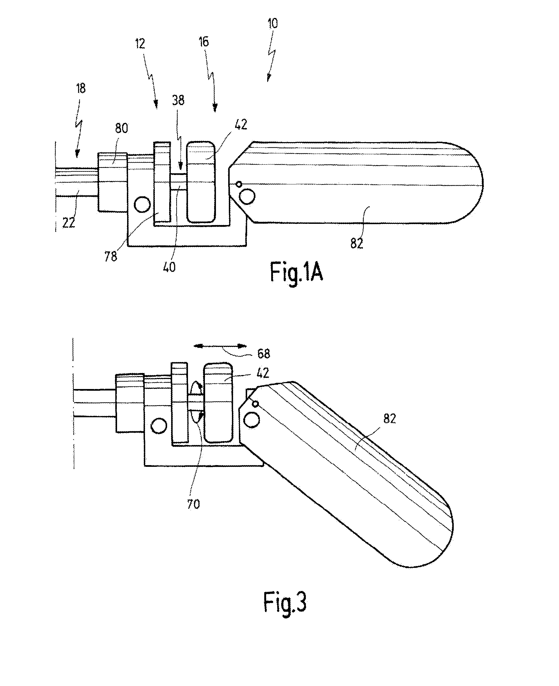
For improving the ergonomy, it is preferred if the handle is inclinable with respect to the longitudinal direction of the shaft.

Problems solved by technology

The known medical instruments have the drawback that, besides the degree of freedom of closing and opening the jaw parts, they have no further degrees of freedom or achieve these only with high friction or additional transmission means due to the fact that the latching mechanism of the known medical instruments is arranged in the handle of these instruments and immobilizes the operating element for closing and opening the jaw parts or the force transmission element itself.
For example, rotating the jaw parts with respect to the shaft is not possible.
A rotation of the jaw parts with respect to the shaft is not possible.
Rotation of the jaw parts is only possible by rotating the whole instrument about its longitudinal axis, which is, however, cumbersome.

Method used


Image

  • Medical instrument for grasping an object, in particular needle holder
  • Medical instrument for grasping an object, in particular needle holder
  • Medical instrument for grasping an object, in particular needle holder

Examples


Embodiment Construction

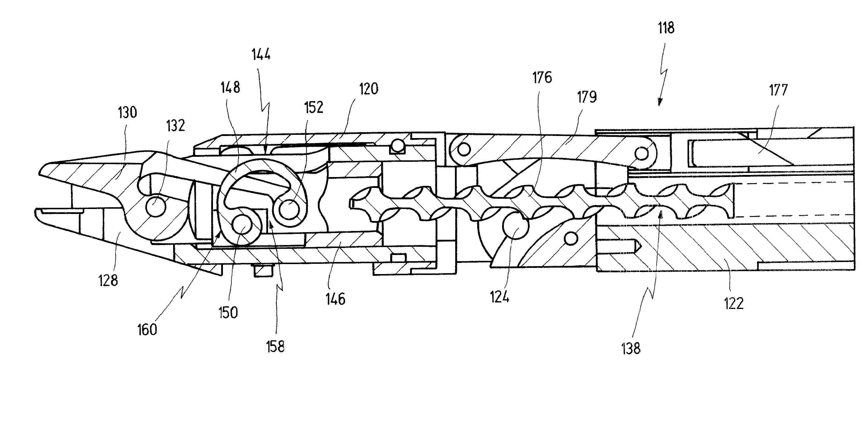
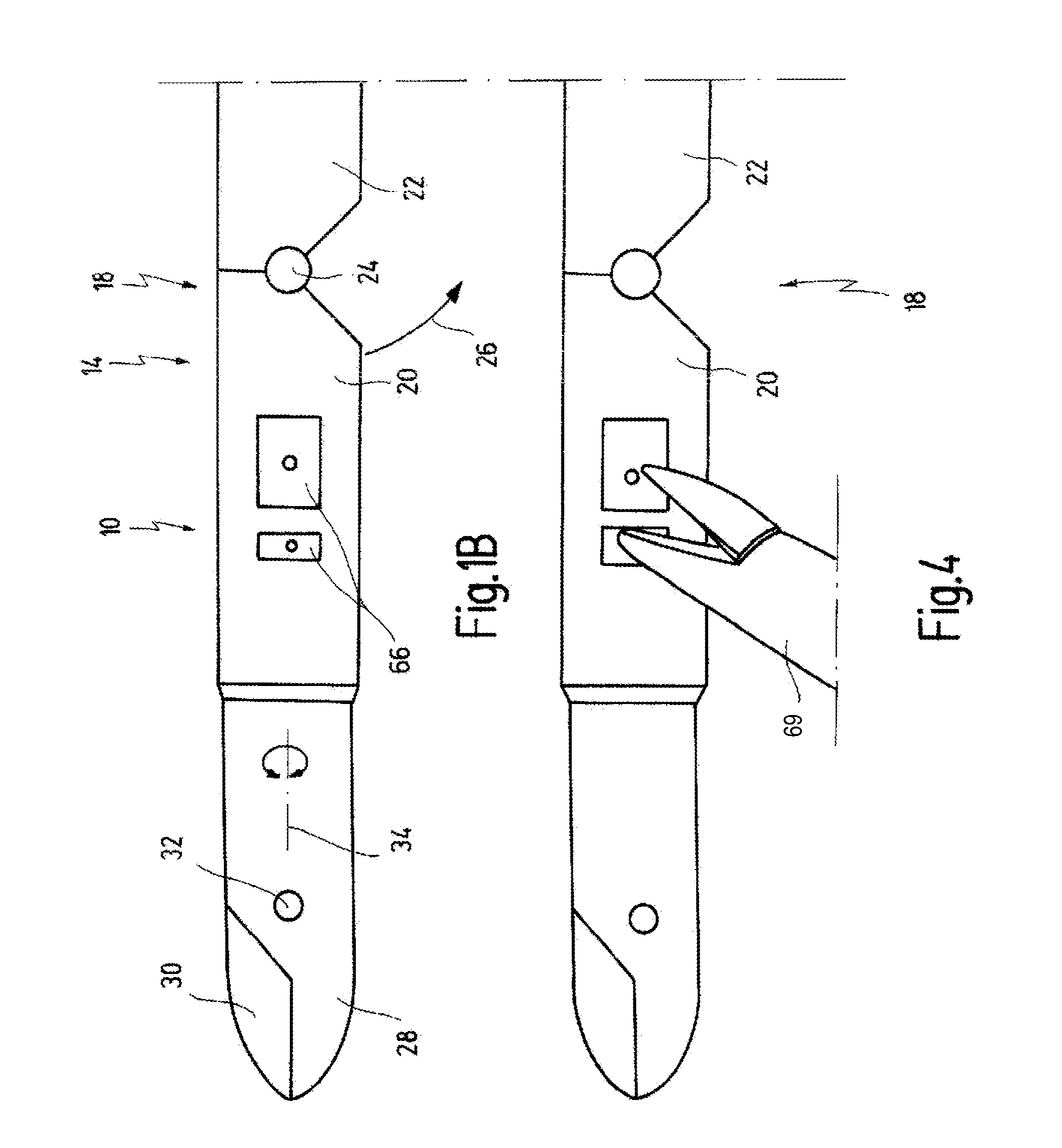
FIGS. 1A and 1B together show a medical instrument for grasping an object, which is generally labeled with reference numeral 10. The medical instrument, in particular, is a surgical needle holder, i.e. the object which can be grasped with the instrument 10 is a surgical needle used in surgery for suturing or ligature operations.

FIG. 1A shows a proximal portion 12 of the instrument 10, and FIG. 1B a distal portion 14 of the instrument 10.

In the proximal portion 12, the instrument 10 comprises a handle 16 which will be described later.

An elongated shaft 18 extends from the handle 16 to the distal portion 14 of the instrument 10. It is to be understood that the shaft 18 has a total length which is larger than the length shown in FIGS. 1A and 1B.

While the shaft 18 is straight in the embodiment shown, the shaft 18 can also have a curvature in a portion between the distal portion 14 and the proximal portion 12 of the instrument.

The shaft 18 further comprises a distal end portion 20 which ...


PUM


Abstract

A medical instrument for grasping an object, in particular a surgical needle holder, including an elongated shaft, two jaw parts arranged at a distal end of the shaft, at least one of the jaw parts being pivotable with respect to the other of the jaw parts between a grasp state for grasping the object between the jaw parts and a release state for releasing the object. A handle is arranged at a proximal end of the shaft and has at least one operating element for moving the at least one pivotable jaw part between the grasp state and the release state via an axially movable force transmission element operatively connected with the at least one operating element and with the at least one pivotable jaw part via an articulated joint. The instrument further includes a latching mechanism for immobilizing the at least one pivotable jaw part in the grasp state.

Description

CROSS-REFERENCE TO RELATED APPLICATIONSThe present application claims priority of European Patent Application No. 06 013 422.8 filed on Jun. 29, 2006.BACKGROUND OF THE INVENTIONThe invention generally relates to medical instruments which are suited for grasping objects. More specifically, the invention relates to surgical needle holders.A needle holder is, for example, known from the firm catalogue “Storz Karl Storz—Endoskope, Volume Laparoscopy, 4. Edition January 2002, Pages NH 1, NH 2 C, NH 3 C, NH4C, NH5C, NH6C, NH7Cand NH8B.While the present invention will be hereinafter described with respect to a medical instrument for grasping a surgical needle, wherein in such case the instrument is also referred to as a needle holder, the invention is not restricted to such an application and other applications are also conceivable. For example, the medical instrument can be used for grasping an implant, for example a bone screw or a bone nail or the like.In case of use of a medical instru...

Claims


Application Information

Patent Timeline
Patent Type & Authority Patents(United States)
IPC IPC(8): A61B17/00
CPCA61B17/062A61B17/29A61B2017/00424A61B2017/2902A61B2017/291A61B2017/2922A61B2017/2926A61B2017/2927A61B2017/2929A61B2017/2939A61B2017/2941A61B2017/2946
Inventor FRANK, TIMOTHY GRAHAMMARTIN, J. DUNCAN S.RUTHERFORD, IANBROWN, STUART I.GOVE, JAMESKELLY, LESLIE
Owner UNIVERSITY OF DUNDEE
Learn More