Syringe

a technology of syringe and needle, which is applied in the field of syringe, can solve the problems of unremovable safety feature, unremovable safety feature, and contaminated needle, and achieve the effect of increasing bridge width, bridge width, and bridge width

Inactive Publication Date: 2012-01-03
CREDENCE MEDSYST
View PDF60 Cites 46 Cited by
  • Summary
  • Abstract
  • Description
  • Claims
  • Application Information

AI Technical Summary

Benefits of technology

[0017]The shaft brake may define a body perimeter and include an aperture and a bridge, the aperture being disposed within the shaft brake and frictionally engaging the plunger shaft, the bridge defining a bridge width and extending radially from the aperture toward the body perimeter, the shaft brake being operative to exert the second frictional force upon the plunger shaft in response to an increase in bridge width, the bridge width increasing in response to the engagement of the ram member with the shaft brake. The ram member may at least partially sever the bridge to increase the bridge width.
[0018]The shaft brake may further include a release member being disposed upon the shaft brake, the bridge width increasing in response to the engagement of the ram member with the release member. The release member may be a shoulder protruding upwardly from the shaft brake opposite the syringe body, and the ram member includes a shoulder press being sized and configured to engage the shoulder upon the piston approaching the bottom syringe body portion, the bridge width increasing in response to the engagement of the shoulder press with the shoulder. The bridge width may increase upon deformation of the bridge in response to engagement of the shoulder press with the shoulder and continued movement of the piston toward the bottom syringe body portion.
[0024]In accordance with yet another implementation of the method, the shaft brake further includes a shoulder being disposed upon the shaft brake and protruding upwardly from the shaft brake opposite the syringe body, and the ram member includes a shoulder press being sized and configured to engage the shoulder upon the piston approaching the bottom syringe body portion, the bridge width increasing in response to the engagement of the shoulder press with the shoulder, and step (b) of the method may further include: engaging the shoulder press with the shoulder; and deforming the bridge to increase the bridge width.

Problems solved by technology

At this point, the needle contaminated and exposed and is a health-risk to the medical professional or other people who may handle the syringe.
In other words, the guidelines suggest that the safety feature itself be unremovable and utilization of the safety feature be unavoidable.
As a result of the foregoing state legislation and agency guidelines, a great amount of time, effort and money has been invested by syringe manufacturers in developing syringes with safety needle designs.
However, the safety syringes that currently exist have been criticized for generally being too expensive to manufacture and having a safety feature that is not an integral part of the safety syringe.
Another criticism includes safety syringes that are not economically feasible because operation of the safety feature is not self evident and therefore additional training is required to use the apparatus effectively.
Additionally, the safety feature of at least one safety syringe is simply ineffective at preventing the transmission of blood-borne pathogens due to “reflux” blood contamination.
However, these safety syringes are typically more expensive because of the required incorporation of additional materials for manufacture.
On the other hand, the median increase in cost for a safety syringe is approximately thirty cents or more.
However, after considering the thousands, if not millions, of needles used each year, the resultant increase in annual cost for utilizing the more expensive safety syringe is unfortunately excessive.
However, due to the configuration and retraction force inherent in the vacuum or spring mechanism aspect of these syringes and others like them, the user of the syringe may often experience difficulties in its use.
Specifically, due to the vacuum pressure or spring mechanism, which exerts an automatic retracting force upon the plunger, the plunger may automatically retract at an undesirable time.
However, automatic retraction of the plunger prior to frictional engagement with the needle holder may often be very problematic.
For example, automatic retraction may make syringe handling very difficult between the time the fluid is drawn to the time the fluid is emptied.
However, while the needle is introduced into the subject, retraction of the plunger could effectively result in drawing fluid therefrom instead of the intended injection of fluid into the subject.
This situation could be very harmful and lead to various unfortunate consequences.

Method used


Image

  • Syringe
  • Syringe
  • Syringe

Examples


Embodiment Construction

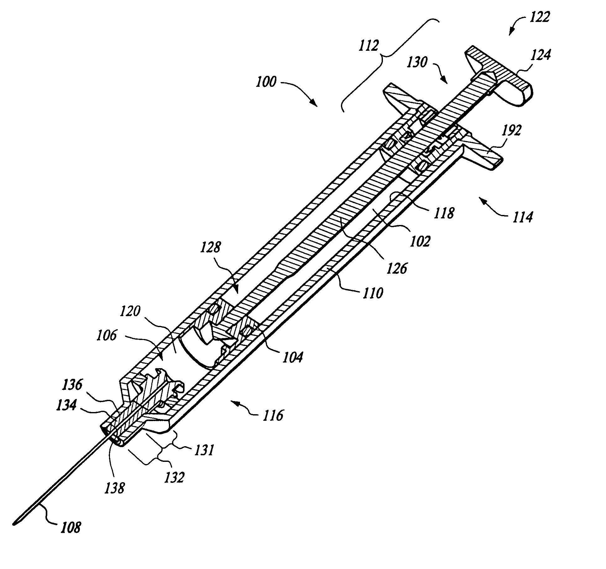
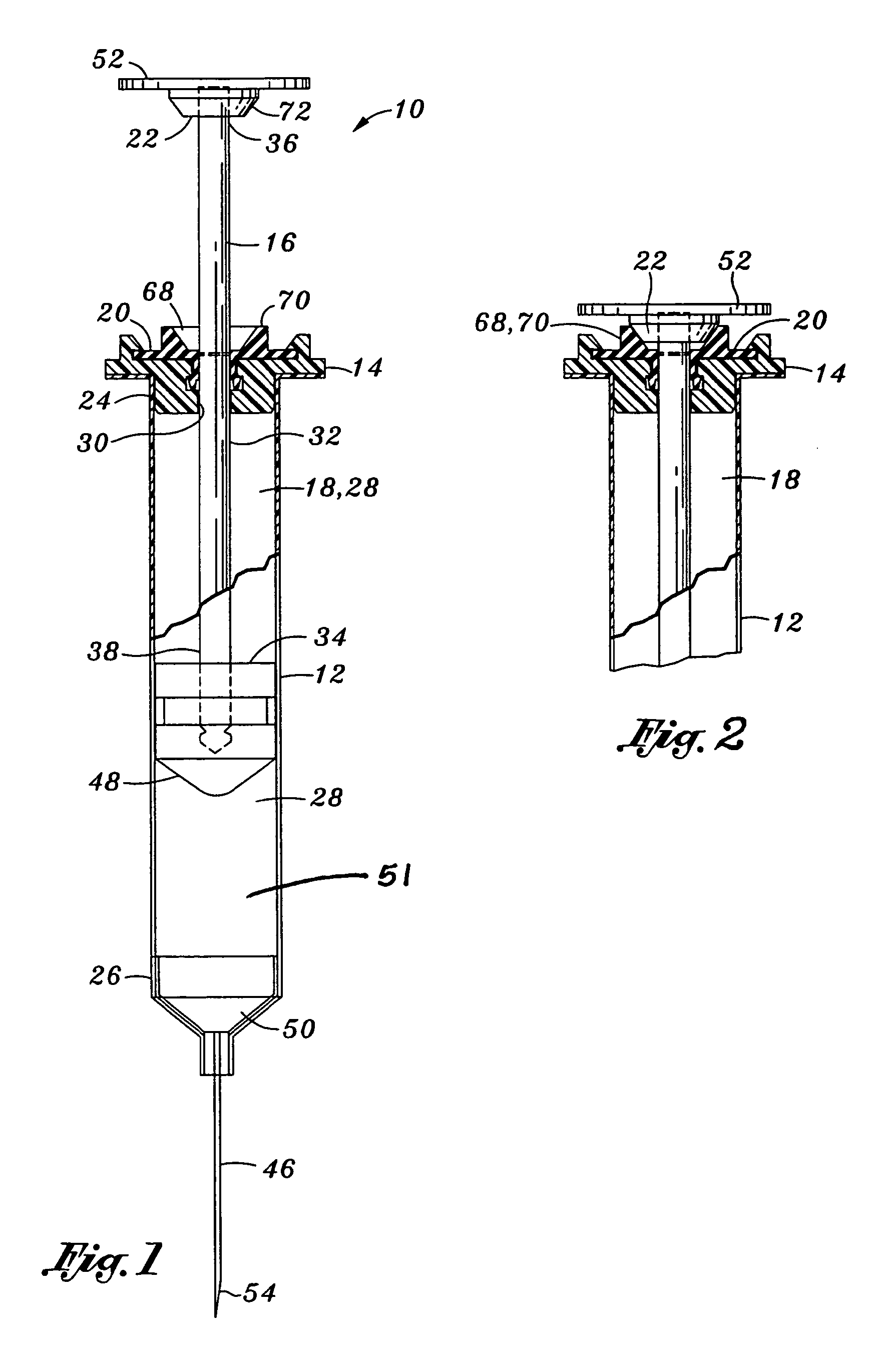
[0054]Referring now to the drawings wherein the showings are for purposes of illustrating the preferred embodiments of the present invention only and not for purposes of limiting the same, FIG. 1 is a cross sectional view of a retractable needle safety syringe 10 with mitigated retraction in accordance with an aspect of the present invention.

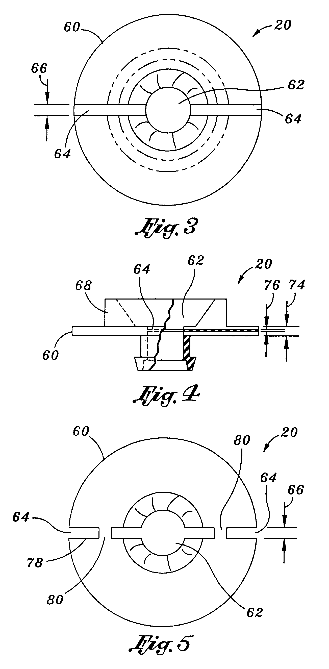
[0055]An embodiment of the syringe comprises a syringe body 12, an attachment base 14, a plunger assembly 16, a variable vacuum compartment 18, a shaft brake 20, and a ram member 22. The syringe body 12 defines opposing top and bottom syringe body portions 24, 26 and includes a syringe cavity 28. The attachment base 14 defines a shaft orifice 30 and is attached to the top syringe body portion 24. The attachment base 14 may form a seal with the body 12. The plunger assembly 16 includes a plunger shaft 32 and a piston 34. The plunger shaft 32 defines opposing top and bottom shaft portions 36, 38. The plunger shaft 32 is disposed throughout the sha...


PUM


Abstract

A retractable needle safety syringe is provided having a braking mechanism. The braking mechanism may be disposed at a proximal portion of a syringe body of the syringe. The braking mechanism may comprise a brake member which is traversable between a braking position and a released position. At the braking position, the brake member frictionally engages an outer surface of the shaft of a plunger of the syringe. The frictional engagement counterbalances a retraction force that urges a piston of the syringe toward a retracted position. When the brake member is traversed to the released position, the brake member does not press against the outer surface of the shaft. As such, the retraction force may traverse the piston toward the retracted position and traverse a needle and needle holder into the body of the syringe.

Description

CROSS-REFERENCE TO RELATED APPLICATIONS[0001]This application is a continuation patent application of U.S. patent application Ser. No. 11 / 439,802, filed May 24, 2006, now U.S. Pat. No. 7,972,300 which claims the benefits of U.S. patent application Ser. No. 11 / 429,301, filed May 5, 2006, which is now U.S. Pat. No. 7,572,247, issued Aug. 11, 2009, which claims the benefits of U.S. patent application Ser. No. 11 / 387,625, filed Mar. 23, 2006, which is now abandoned, which claims the benefits of U.S. Provisional Application No. 60 / 679,113 entitled “IMPROVED SYRINGE” filed May 9, 2005, which is now expired, the entirety of the disclosures of which are expressly incorporated herein by reference.STATEMENT RE: FEDERALLY SPONSORED RESEARCH / DEVELOPMENT[0002]Not ApplicableBACKGROUND OF THE INVENTION[0003]Hypodermic needles are used on a regular basis by medical professionals such as doctors, nurses and other medicine related fields. The typical hypodermic needle has a syringe body with a hollow...

Claims


Application Information

Patent Timeline
Patent Type & Authority Patents(United States)
IPC IPC(8): A61M5/00
CPCA61M5/3234A61M2005/3224A61M2005/3242
Inventor SMITH, JEFFREYTHAYER, DANIELBARE, REX O.
Owner CREDENCE MEDSYST
Why Eureka
Try Eureka