

Safety syringe with needle retracting mechanism
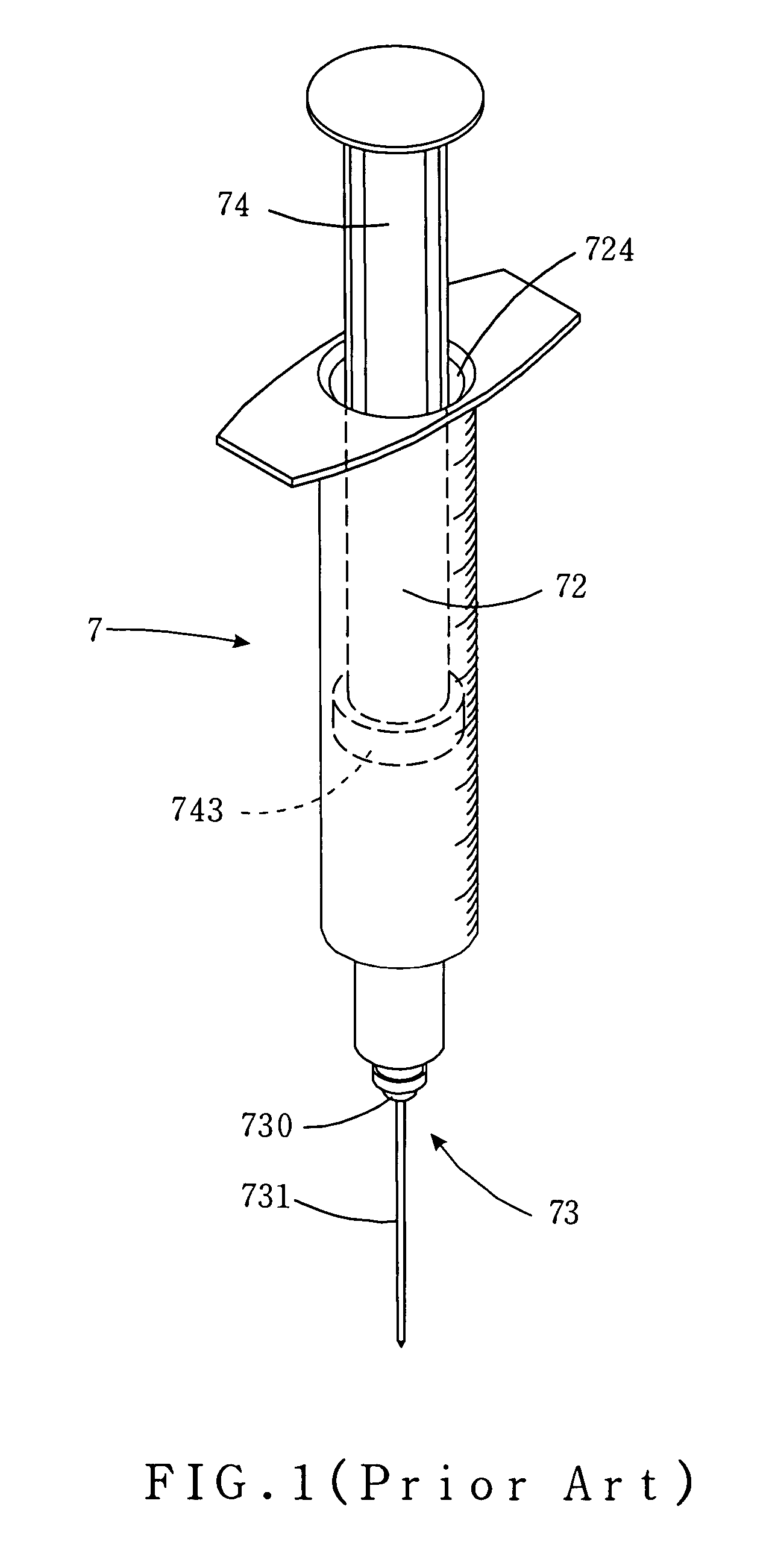
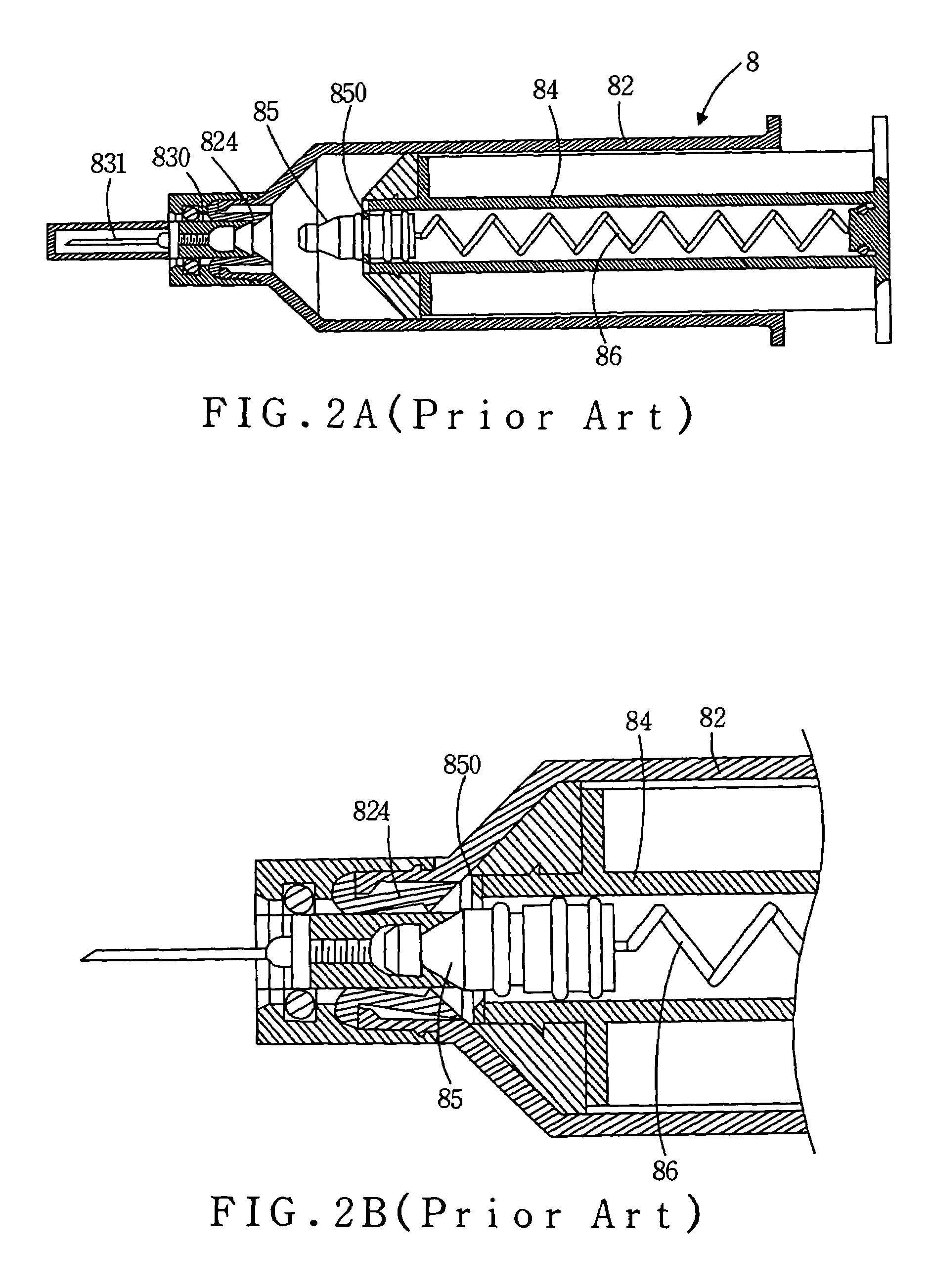
a safety syringe and needle technology, applied in the field of safety syringes, can solve the problems of increasing the cost the delicate process of fabricating the elements of the tiny syringe, and the syringe b>7/b> may be too expensive for selling, and achieves the effect of convenient fabricated elements and convenient operation
- Summary
- Abstract
- Description
- Claims
- Application Information
AI Technical Summary
Benefits of technology
Problems solved by technology
Method used
Image

Examples
first embodiment
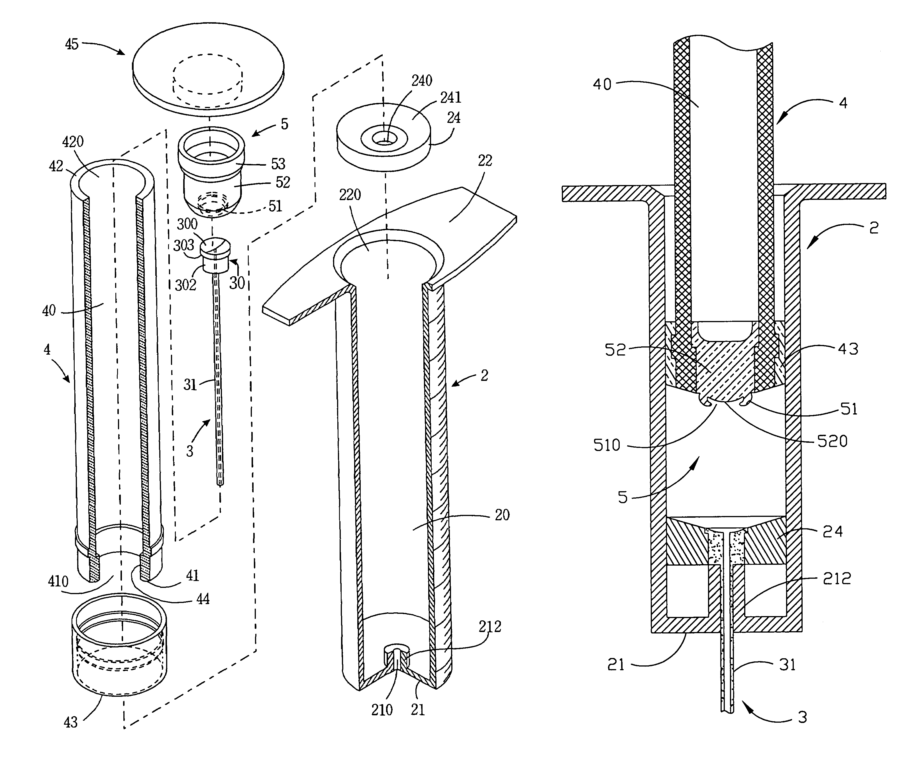
[0027]As shown in FIGS. 3A-3D, the present invention provides a safety syringe including a syringe barrel 2, a needle unit 3 set in the front end of the syringe barrel 2, a plunger 4 movably disposed within the syringe barrel 2 and a flexible sealing member 5 disposed movably within the front end of the plunger 4.
[0028]The syringe barrel 2 includes a barrel body 20, a front-end wall 21 and a rear end wall 22. A front opening 210 and the front-end wall 21 are integrally formed. A rear opening 220 is formed integrally with the rear end wall 22. The cross-sectional area of the rear opening 220 is slightly larger than the cross-sectional area of the plunger 4; thus the plunger 4 can be inserted into the syringe barrel 2. A spacer portion 212 is disposed on the front end wall 21, wherein the front opening 210 penetrates the spacer portion 212. The spacer portion 212 and the barrel body 20 can be formed integrally. However, the spacer portion 212 may be an independent element set on the f...
third embodiment
[0036]It is to be understood that many modifications and variations of the structures of the annular flexible holder-supporting seat, the sealing member and the needle unit, and the method for disposing the sealing member are possible in light of the above teachings. FIGS. 5A-5D illustrate the present invention. The side of the central hole 240 of the flexible holder-supporting seat 24 fastens a U-shaped flexible element 6 including a hole 60. The U-shaped flexible element 6 is clenched by the flexible holder-supporting seat 24 and the needle holder 302′. The needle 31 projected from the U-shaped flexible element 6 is clenched by the hole 60. The external diameter of the U-shaped flexible element 6 is slightly larger than the internal diameter of the plunger 4. The needle 31 is fastened by the needle holder 302′ and projected from the needle holder 302′. The shape of the flexible sealing member 5 of this embodiment is also different from the shape of the flexible sealing member 5 of...
fourth embodiment
[0037]As shown in FIG. 6, the present invention provides a safety syringe including a syringe barrel 2 with a different front-end wall 21. The front-end wall 21 includes a front opening 210′ for fastening a needle 31, wherein the needle 31 projects from the front end wall 21. The needle 31 stabs into the sealing rear portion 520 to seal the needle 31 and combine the needle unit 3 with the U-shaped flexible element 6 and the flexible sealing member 5 when the plunger 4 is pushed to contact with the flexible holder-supporting seat 24. When the plunger 4 is continuously pushed, the flexible holder-supporting seat 24 is pushed by the plunger 4 to slip and release the U-shaped flexible element 6. Because the 210 prop up the needle holder 302, the U-shaped flexible element 6 is also pushed by the plunger 4 until the bottom of the U-shaped flexible element 6 contacting with the needle holder 302. The needle 31 stabs into the flexible-sealing member 5 deeper when the U-shaped flexible eleme...
PUM
 Abstract
Description
Claims
Application Information