Injection System With Hidden Needles

a technology of injection system and needle, which is applied in the field of injection system with hidden needle, can solve the problems of affecting drug absorption rate, requiring excessive power to achieve the depth normally required for many intramuscular injections, and the psychological implications of using hypodermic needle may be even more profound. , to achieve the effect of predictable injection

Active Publication Date: 2008-02-14
AVANT MEDICAL CORP
View PDF71 Cites 48 Cited by
  • Summary
  • Abstract
  • Description
  • Claims
  • Application Information

AI Technical Summary

Benefits of technology

[0008]In accordance with the present invention, an auto-injector is provided that is effectively self-contained inside the interior of a housing. The intent here is to keep all operational components of the auto-injector, and most importantly its needle, out-of-sight and hidden from the view of the user. As envisioned for the present invention, this concealment of the needle is accomplished before, during and after an injection. To do this, the needles that are to be used with the auto-injector can be preloaded and supplied inside a casement (magazine, drum, etc.) for insertion into or for attachment to the auto-injector. The needle casement can then be used, and subsequently discarded as a unit without the user ever seeing or handling any of the needles. Some additional benefits of the present invention are also noteworthy. Specifically, with a completely enclosed operation, there is increased safety when using the auto-injector of the present invention. Moreover, each needle is used only once. This fact, alone, helps prevent contamination and insures that the structural integrity and lubricity of each needle are maintained until there is an actual use of the needle.
[0015]It is to be appreciated that the collar on the needle can be caused to interact with the housing during an operation of the auto-injector to limit the depth to which the needle will penetrate into the patient (user). It is also to be appreciated that the auto-injector of the present invention may include a vacuum system that can be activated to stabilize the skin of the patient at the injection site, to thereby provide for a more predictable injection.

Problems solved by technology

Although needleless injectors are particularly efficacious for subcutaneous injections, they typically require excessive power to achieve the depth normally required for many intramuscular injections.
An improper engineering of some, or all, of these considerations may affect drug absorption rates or cause pain.
Apart from these considerations, however, the psychological implications that result from using a hypodermic needle may be even more profound.
Further, this aversion frequently evokes fear of injection site reactions (e.g. pain and bruising) that may, or may not, be real.
And, when the injection needs to be self-administered, the task itself will often cause a hesitation or paralysis on the part of the user that prevents accomplishing a proper injection.
In this context, it is known that “needle anxiety” has caused some patients to unnecessarily delay the beginning of a therapy regime for extended periods of time (e.g. several years).
Nevertheless, prior to use, auto-injectors invariably involve many complicated steps for set-up.
Unfortunately, these operations typically expose the user to a visual contact with a needle that can trigger “needle anxiety.” Also, injections with an auto-injector can be perceived to be more painful than a regular syringe injection due to the auto-injector's response to the drive mechanism actuation.
Further, auto-injectors are typically not configured to conveniently provide for the sequence of multi-dose injections that may be required for many treatment regimes.

Method used


Image

  • Injection System With Hidden Needles
  • Injection System With Hidden Needles
  • Injection System With Hidden Needles

Examples


embodiment 40

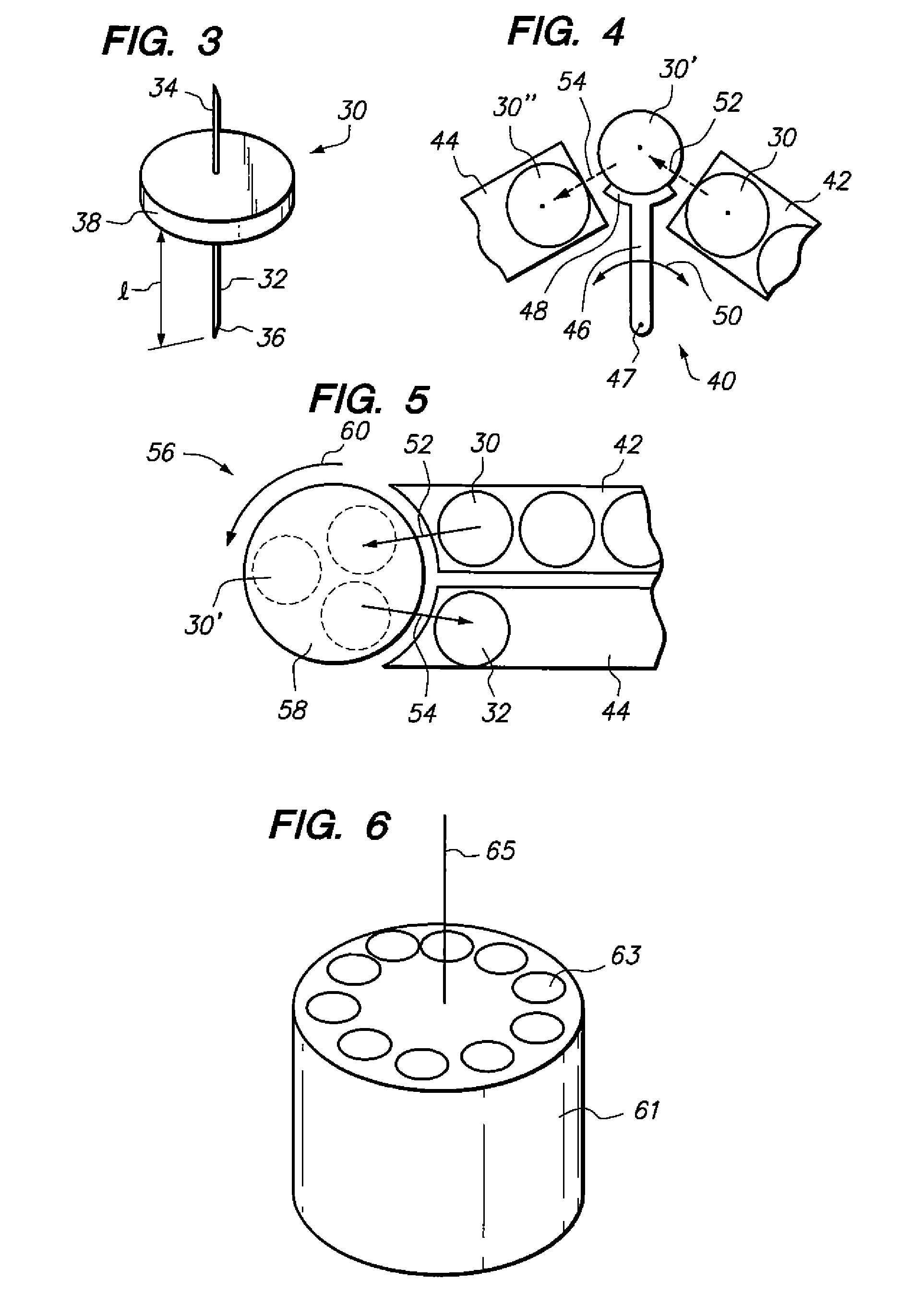
[0029]In FIG. 4 an embodiment of the needle holder 28 is shown, and is generally designated 40. This particular embodiment 40 of the needle holder 28 is provided to move a needle unit 30 from a magazine 42, and to then subsequently move it to a storage location 44. To do this, the embodiment 40 includes an arm 46 that rotates about a point 47. A grip 48 is located at one end of the arm 46. Thus, as the arm 46 is rotated back and forth in the direction of the arrows 50, the grip 48 can, in sequence, retrieve a needle unit 30 from the magazine 42 and then move it along a path 52 to a location (shown as needle unit 30′). At this location, the needle unit 30′ is positioned to cooperate with the connector 26. After its cooperation with the connector 26, needle unit 30′ is then moved by the grip 48 along a path 54 to the storage location 44 (i.e. needle unit 30″) where it will be stored for subsequent disposal.

embodiment 56

[0030]FIG. 5 shows another embodiment of the needle holder 28 that is generally designated 56. For the embodiment 56 of the needle holder 28, a carousel 58 is employed to move the needle unit 30 into location for cooperation with the connector 26. More specifically, for the embodiment 56 a needle unit 30 is retrieved from the magazine 42 and moved along path 52 onto the carousel 58. The carousel 58 then rotates in the direction of the arrow 60 to the location of needle unit 30′ where it cooperates with the connector 26 (see FIG. 7). After its cooperation with the connector 267 the needle unit 30′ is then moved by the carousel 58 for further movement along a path 54 to the storage location 44 (shown as needle unit 30″). There it will be stored for subsequent disposal.

[0031]In FIG. 6, a cassette 61 is shown as yet another embodiment of the needle holder 28. Specifically, the cassette 61 is generally cylindrical shaped, as shown, and it is formed with a plurality of receptacles 63. As ...


PUM


Abstract

An auto-injector confines all functional components inside an enclosed housing, to keep its needle out-of-sight, at all times. Within the housing, a needle holder positions a needle at a location. A drive mechanism then simultaneously engages the needle with a fluid source and accelerates it with a predetermined momentum for insertion into a patient. After fluid delivery, the withdrawn needle is moved to storage within the housing for subsequent disposal.

Description

FIELD OF THE INVENTION[0001]The present invention pertains generally to systems and devices for using a needle to inject fluid medicaments into the body of a patient. More particularly, the present invention pertains to auto-injectors that can be used by a caregiver, or used individually by a patient to self-administer a fluid medicament. The present invention is particularly, but not exclusively, useful as a system and method for conveniently self-administering an injection without ever subjecting the user to a visual confrontation with the needle.BACKGROUND OF THE INVENTION[0002]Injectable drugs are necessary for numerous medical reasons, and they are typically used in a wide variety of applications. Consequently, various types of drug delivery systems have been developed to meet the many diverse needs of particular medical procedures. With any injectable drug delivery system, however, both physical and psychological implications are involved. Both are important, and both deserve ...

Claims


Application Information

Patent Timeline
Patent Type & Authority Applications(United States)
IPC IPC(8): A61M5/20A61M5/00
CPCA61M5/008A61M5/204A61M5/32A61M5/326A61M5/34A61M5/425A61M5/46A61M2005/004A61M5/3287
Inventor SLATE, JOHN B.BARNES, ANDREW C.MAGERS, COREY M.
Owner AVANT MEDICAL CORP
Why Eureka
Try Eureka