Eureka AIR delivers breakthrough ideas for toughest innovation challenges, trusted by R&D personnel around the world.

Buoy

a technology of buoys and buoys, applied in the field of buoys, can solve the problems of not being able to completely submerge the buoy, and the downward force is not enough, so as to reduce the angle of inclination, reduce drag forces, and smooth rounded profile

Inactive Publication Date: 2011-03-08
ULTRA ELECTRONICS LTD
View PDF15 Cites 23 Cited by
  • Summary
  • Abstract
  • Description
  • Claims
  • Application Information

AI Technical Summary

Benefits of technology

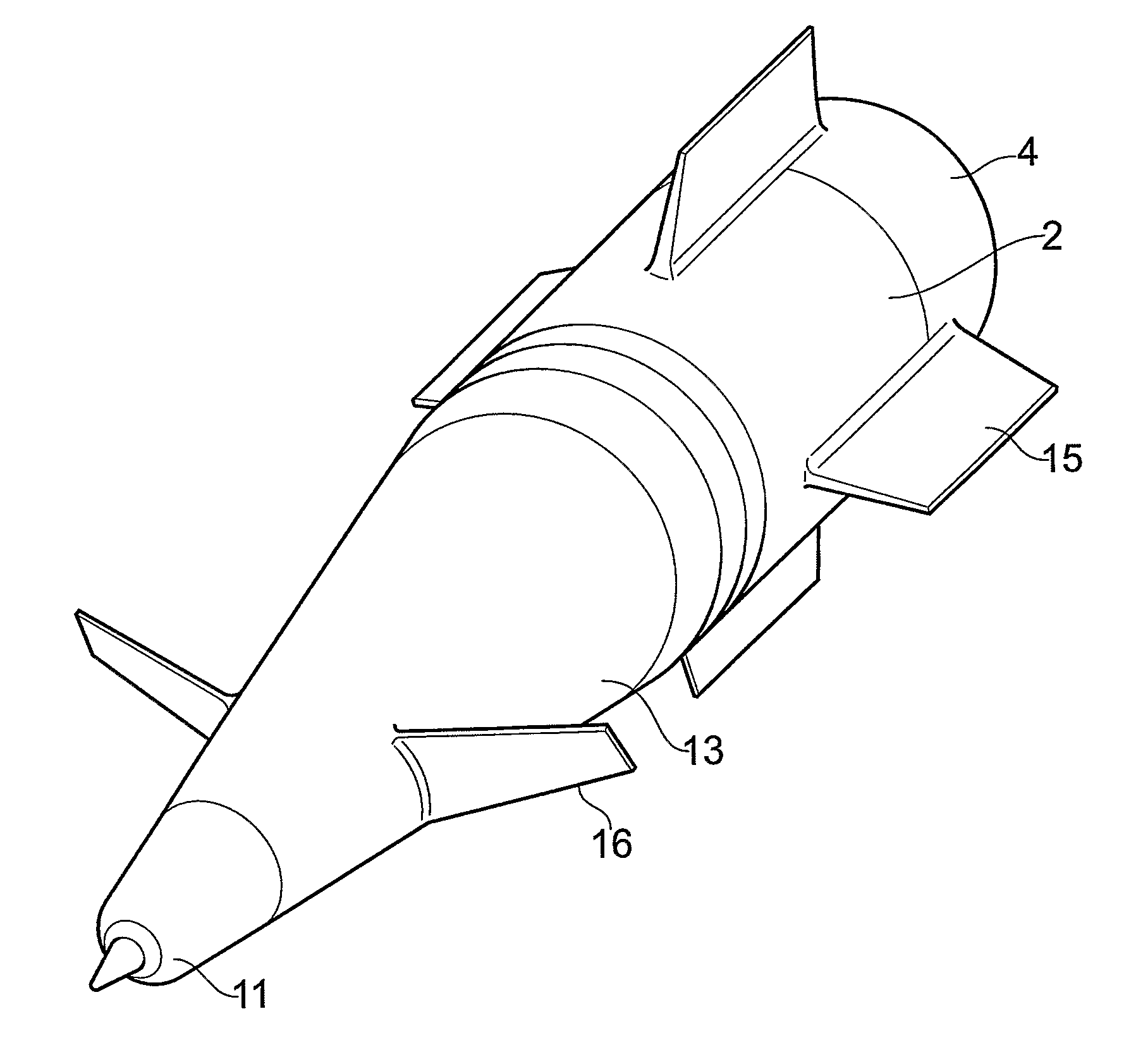
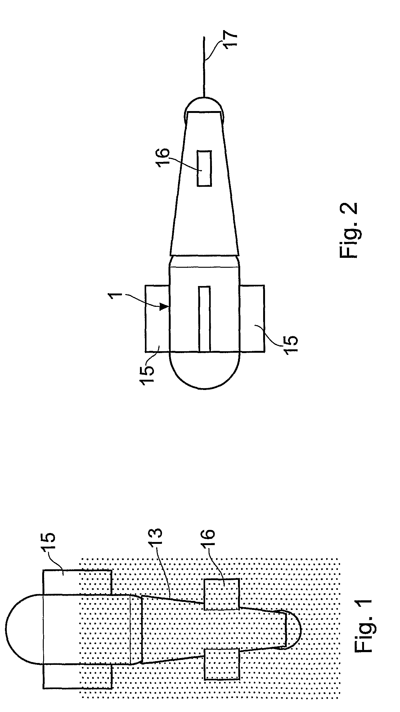
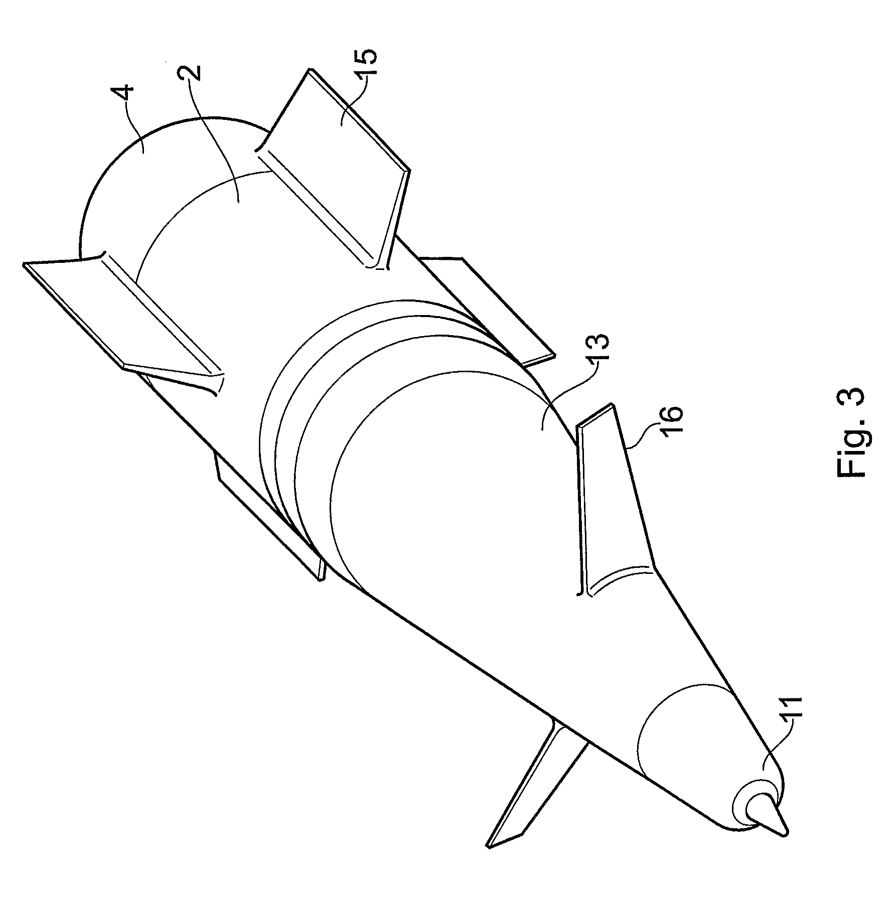
[0006]The first hydrodynamic surface may comprise a fin or fins which are set at an angle of inclination on the casing of the buoy to generate said downward force and to reduce the angle of inclination as the buoy aligns with the tow direction with increasing through water speed. The second hydrodynamic surface may comprise a fin or fins set at an angle of inclination on the casing of the buoy to generate said upward force and to increase the angle of inclination as the buoy aligns with the tow direction with increasing through water speed. Preferably, the first and second hydrodynamic surfaces are formed as rear and front fins, respectively, in the towing directions, and vortex flows generated by the front fins may enhance the downward force of the rear fins.
[0008]The casing of the buoy preferably comprises a cylindrical body containing electrical equipment, and a hemispherical top which closes the upper end of the cylinder and serves as a radome, and a hemispherical bottom which closes the lower end of the cylinder and supports a downwardly extending elongate member carrying a mass at its lower end. The lower mass serves to lower the centre of gravity of the buoy so that it is below the centre of buoyancy. The buoy then floats upright and has good roll stability. If a fairing is provided around the downwardly extending member and mass, it will also enclose a mass of water, which will also increase surface stability. In a preferred embodiment, the lower mass takes the form of an induction core through which a battery in the buoy can be charged by inductive coupling with an external power source through a docking system with which the lower end of the buoy docks once recovered.

Problems solved by technology

The tension in a tether used to recover a buoy will create a downward force but may not be enough to submerge the buoy completely or to maintain it at an adequate depth.

Method used


Image

  • Buoy
  • Buoy
  • Buoy

Examples


Embodiment Construction

[0016]The buoy illustrated in FIG. 1 comprises a float chamber 1 containing electrical equipment for transmitting and receiving radio signals. The float consists of a cylindrical member 2 closed top and bottom by a hemispherical cap 4, 3 so as to form a robust pressure vessel. The internal equipment includes an antenna 5 located at the upper end of the float 1 within the upper hemispherical cap 4; the cap 4 acts as a radome.

[0017]A rod 6 is connected to the lower hemispherical cap 3 and projects downwardly from it coaxially with the float 2 and carries a mass 7 at its lower end. The purpose of the mass 7 is to lower the centre of gravity of the buoy so that it is below the centre of buoyancy and thereby increases the surface stability of the float. This arrangement is illustrated schematically in FIG. 5, which shows the centre of gravity 8 and the centre of buoyancy 9. The magnitude of the mass is selected in relation to the mass of the other components of the buoy, but the overall ...


PUM


Abstract

A buoy is provided with first and second fixed hydrodynamic surfaces (15,16). When the buoy is towed through water by a tether (17), the first hydrodynamic surface (15) generates a downward force that reduces with increased speed through the water. The second hydrodynamic surface (16) generates an upward force that increases with increased speed through the water so that the buoy dives up to an upper critical speed through the water speed and rises beyond said upper critical speed through the water. The downward force of the first hydrodynamic surface (15) overcomes the buoyancy of the buoy at a lower critical speed through the water above, which the buoy dives. The hydrodynamic surface (15) comprises first fins (15) mounted on an outer casing (1) of the buoy and are spaced angularity and extend parallel to the center axis of the buoy which is substantially aligned with the direction of towing. The second hydrodynamic surface (16) comprises second fins (16) mounted on the outer casing arranged upstream of the first fins (15) in the direction of towing. The second hydrodynamic surface (16) is set at an angle of incidence such that it creates a stalled flow condition at said upper critical speed through the water.

Description

TECHNICAL FIELD[0001]This invention relates to a buoy adapted to be deployed so that it floats at the water surface and adapted to be recovered by an underwater vessel.[0002]The natural buoyancy of a buoy will generate an upward force that will tend to return it to the surface once submerged. The tension in a tether used to recover a buoy will create a downward force but may not be enough to submerge the buoy completely or to maintain it at an adequate depth.DISCLOSURE OF THE INVENTION[0003]According to the present invention, a buoy is provided with first and second fixed hydrodynamic surfaces, which when the buoy is towed through water by a tether, the first hydrodynamic surface generates a downward force that reduces with increased through water speed, and the second hydrodynamic surface generates an upward force that increases with increased through water speed, so that the buoy dives at speeds up to an upper critical through water speed and rises at speeds beyond said upper crit...

Claims


Application Information

Patent Timeline
Patent Type & Authority Patents(United States)
IPC IPC(8): B63G8/14B63B22/00B63B22/18
CPCB63B22/003B63B22/18B63B21/56
Inventor JABER, BARRY N.WIGNALL, ALANMARTIN, JOHN D.
Owner ULTRA ELECTRONICS LTD
Why Eureka
Eureka Blog
Learn More